TIDUEZ4 May 2021
- Description
- Resources
- Features
- Applications
- 5
- 1System Description
-
2System Overview
- 2.1 Block Diagram
- 2.2 Highlighted Products
- 2.3 Design Considerations
- 3Hardware, Software, Testing Requirements, and Test Results
- 4Design and Documentation Support
- 5About the Author
3.4.1 Power Supply Rails and Current Consumption
Standby Mode: The CC1352R LaunchPad is mounted on the camera module. The CC1352R wakes up the system (Wi-Fi and image processor) on receiving a wake-up trigger. This wake-up trigger can be a PIR activity or video doorbell button press or a network trigger. If no trigger is received, the system is in standby mode. This mode also serves as a low-power mode for the camera. In this state, only battery gauging is supported at regular intervals and the rest of the blocks are in sleep or hibernate mode. The current drawn from 5 V battery in this mode is approximately 2 mA. Note that CC1352R software example is not optimized for power: Wake on radio also consumes more power. A developer can optimize the sensors on the Launchpad and the RX/TX duration of CC1352R to reduce the current consumption. Longer preamble on TX will increase the response time, but decrease the current consumption on the RX side.
Active Mode: Once a wake-up trigger is received by the CC1352R, it activates the main host MCU, that is, Wi-Fi, video encoder and the necessary power rails. This state is referred to as active mode for the camera. Here, additional functions are available: ambient light sensing, video streaming over Wi-Fi or over USB. The current drawn from a 5 V battery in active mode is approximately 200 mA during video streaming. Note that CC3235MODS SW is not optimized for power. Table 3-1 illustrates the test conditions and the expected current consumption from the battery rail.
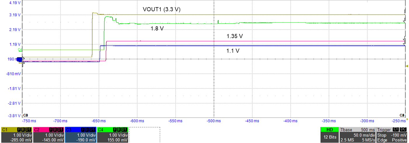
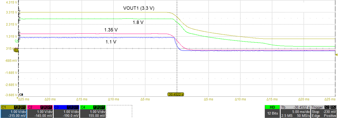
Figure 3-20 and Figure 3-21 shows the power-up and power-down sequence as seen in the camera module. Individual delays for each rail can be modified by setting the appropriate R/C in the schematic design to meet the power up/down requirements as suggested in the OA7000 datasheet.
| STATE | TEST CONDITIONS | CURRENT | VOLTAGE RAIL |
|---|---|---|---|
| Standby mode | Wireless camera module with CC1352R LaunchPad mounted | 2 mA | 5 V battery connection |
| Functions operational: battery-gauging, wake-up based on network, doorbell, PIR; Wi-Fi in hibernate mode | |||
| Active mode | Additional functions: Wi-Fi, sensing, video encoder enabled and powered-up Functions not enabled: IR LED drive, IR cut filter and audio | 178 mA | |
| Active mode with video streaming | Additional functions: video streaming on-going | 212 mA |
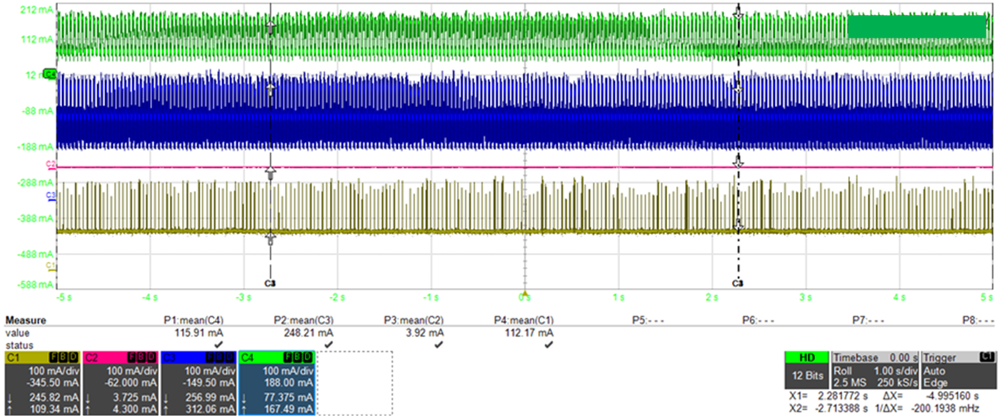
 Figure 3-18 Current Consumption From Each Rail: C1-VOUT1 (3.3 V), C2-1.35 V, C3-1.1 V, C4-1.8 V
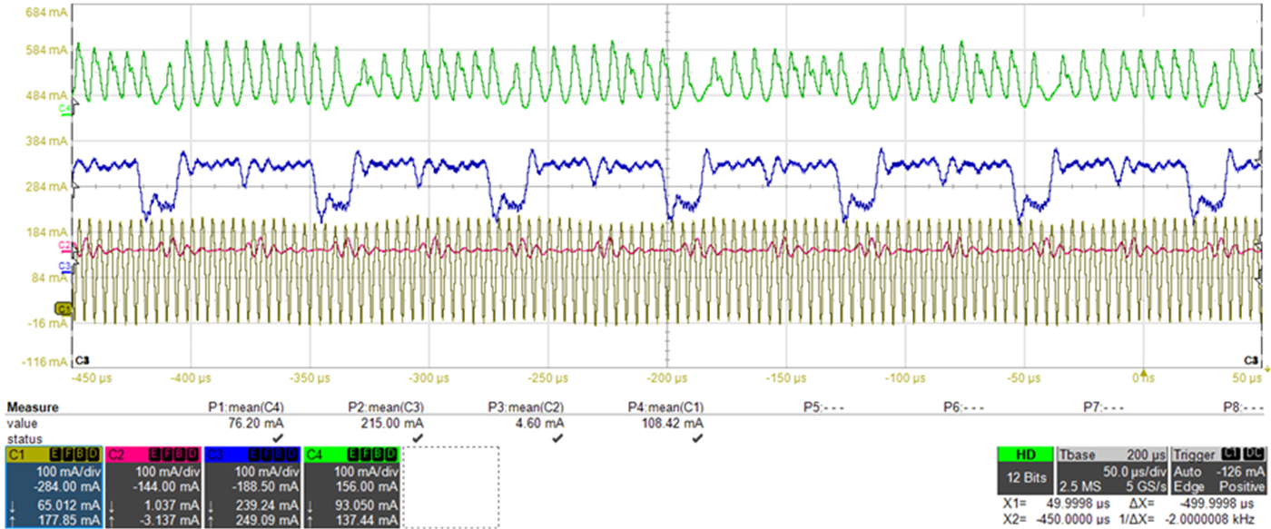
 Figure 3-19 Current Consumption Zoomed in From Each Rail: C1-VOUT1(3.3 V), C2-1.35 V, C3-1.1 V, C4-1.8 V
 Figure 3-20 Power-up Sequence
 Figure 3-21 Power-down Sequence