TIDUF13 November 2022 ADS117L11 , ADS127L11
- Description
- Resources
- Features
- Applications
- 5
- 1System Description
- 2System Overview
- 3System Design Theory
- 4Hardware, Software, Testing, and Test Results
- 5Design and Documentation Support
- 6About the Author
4.4.5 Clock Image Rejection
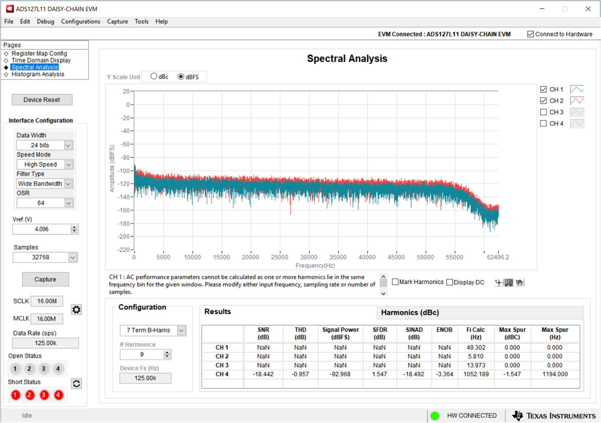
The frequency-domain plot shown in Figure 4-16 were taken at 10-VPP, 16.002-MHz sinusoidal signal applied to ch1. This setting simulates the clock image frequency at the input. Output spectrum shows no sign of clock intermodulation, and that the clock rejection is below the noise level.
 Figure 4-16 Frequency-Domain Plot of 10-VPP Clock Image Input at Channel 1