TIDUF18A October 2022 – February 2024
- 1
- Description
- Resources
- Features
- Applications
- 6
- 1 CLLLC System Description
- 2 CLLLC System Overview
- 3 Totem Pole PFC System Description
- 4 Highlighted Products
-
5 Hardware, Software, Testing Requirements, and Test Results
- 5.1 Required Hardware and Software
- 5.2
Testing and Results
- 5.2.1 Test Setup (Initial)
- 5.2.2
CLLLC Test Procedure
- 5.2.2.1 Lab 1. Primary to Secondary Power Flow, Open Loop Check PWM Driver
- 5.2.2.2
Lab 2. Primary to Secondary Power Flow, Open Loop CheckPWM
Driver and ADC with Protection, Resistive Load Connected on Secondary
- 5.2.2.2.1 Setting Software Options for Lab 2
- 5.2.2.2.2 Building and Loading the Project and Setting up Debug Environment
- 5.2.2.2.3 Using Real-time Emulation
- 5.2.2.2.4 Running the Code
- 5.2.2.2.5 Measure SFRA Plant for Voltage Loop
- 5.2.2.2.6 Verify Active Synchronous Rectification
- 5.2.2.2.7 Measure SFRA Plant for Current Loop
- 5.2.2.3 Lab 3. Primary to Secondary Power Flow, Closed Voltage Loop Check, With Resistive Load Connected on Secondary
- 5.2.2.4 Lab 4. Primary to Secondary Power Flow, Closed Current Loop Check, With Resistive Load Connected on Secondary
- 5.2.2.5 Lab 5. Primary to Secondary Power Flow, Closed Current Loop Check, With Resistive Load Connected on Secondary in Parallel to a Voltage Source to Emulate a Battery Connection on Secondary Side
- 5.2.3 TTPLPFC Test procedure
- 5.2.4 Test Results
- 6 Design Files
- 7 Software Files
- 8 Related Documentation
- 9 Terminology
- 10About the Author
- 11Revision History
3.2 Totem-Pole Bridgeless PFC Operation
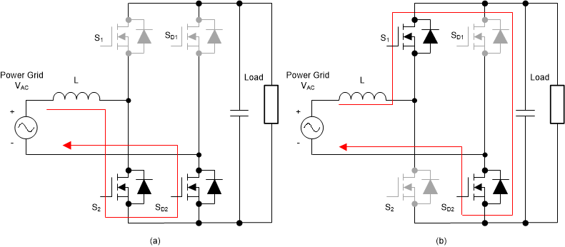
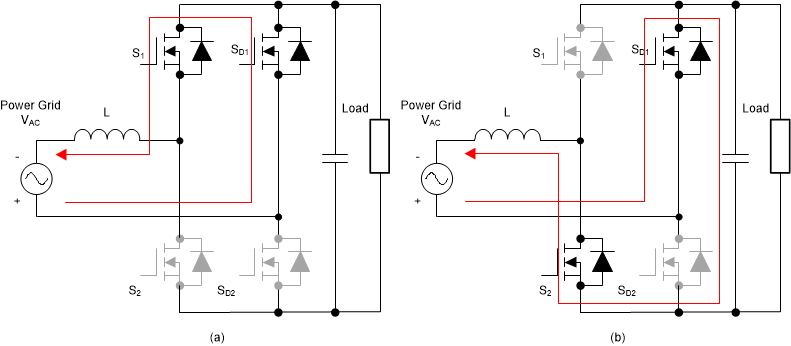
The totem-pole PFC operates in the positive and negative cycles of the AC mains input, respectively, and determines the current flow depending on how the high frequency GaN MOSFETs are switched (see Figure 3-2 and Figure 3-3, respectively).
The high-frequency GaN MOSFETs together with the inductor create a synchronous mode boost converter. During the positive half cycle, S2 is the boost switch which is driven with duty cycle D and S1 is driven with a complementary pulse-width modulation (PWM) signal (1-D). Figure 3-2 (A) shows the direction in which the current flows. Similarly, during the period when S2 is switched with 1-D, S1 is switched with D; Figure 3-2 (B) shows the direction in which the current flows. Note that, during this cycle, SD2 conducts continuously.
During the negative half cycle, the operation is similar except that the role of the high-side- and low-side, high-frequency switches are swapped. Figure 3-3 shows the direction in which the current flows. Note that, during this cycle, SD1 conducts continuously.
 Figure 3-2 Totem-Pole Bridgeless PFC Operation During Positive Half Cycle: (A) While S2 is Switched ON (B) While S2 is Switched OFF
 Figure 3-3 Totem-Pole Bridgeless PFC Operation During Negative Half Cycle: (A) While S1 is Switched ON (B) While S1 is Switched OFF
This reference design uses GaN FETs (LMG3522R030-Q1) and TI’s C2000™ Piccolo™ (TMS320F280039C) high-performance MCU. The high-frequency GaN FETs operate at a 120-kHz switching frequency and the pair of Si MOSFETs operate at the line frequency (approximately 45 Hz to 60 Hz). Thus the conduction path includes one GaN switch and one low-frequency Si switch with significantly-reduced conduction losses. The use of two-channel interleaving to reduce conduction loss and input current ripple. Test results demonstrate a high efficiency above 98.5%.