TIDUF23 may   2023


  1.   Description
  2.   Resources
  3.   Features
  4.   Applications
  5.   5
  6. 1System Description
    1. 1.1 Key System Specifications
  7. 2System Overview
    1. 2.1 Block Diagram
    2. 2.2 Design Considerations
    3. 2.3 Highlighted Products
      1. 2.3.1  UCC5880-Q1
      2. 2.3.2  AM2634-Q1
      3. 2.3.3  TMS320F280039C-Q1
      4. 2.3.4  UCC14240-Q1
      5. 2.3.5  UCC12051-Q1
      6. 2.3.6  AMC3330-Q1
      7. 2.3.7  TCAN1462-Q1
      8. 2.3.8  ISO1042-Q1
      9. 2.3.9  ALM2403-Q1
      10. 2.3.10 LM5158-Q1
      11. 2.3.11 LM74202-Q1
    4. 2.4 System Design Theory
      1. 2.4.1 Microcontrollers
        1. 2.4.1.1 Microcontroller – C2000™
        2. 2.4.1.2 Microcontroller – Sitara™
      2. 2.4.2 Isolated Bias Supply
      3. 2.4.3 Power Tree
        1. 2.4.3.1 Introduction
        2. 2.4.3.2 Power Tree Block Diagram
        3. 2.4.3.3 12 V Distribution and Control
        4. 2.4.3.4 Gate Drive Supply
        5. 2.4.3.5 5-Volt Supply Domain
        6. 2.4.3.6 Current and Position Sensing Power
  8. 3Hardware, Software, Testing Requirements, and Test Results
    1. 3.1 Hardware Requirements
      1. 3.1.1 Hardware Board Overview
        1. 3.1.1.1 Control Board
        2. 3.1.1.2 MCU Control Card – Sitara™
        3. 3.1.1.3 MCU Control Card – C2000™
        4. 3.1.1.4 Gate Driver and Bias Supply Board
        5. 3.1.1.5 DC Bus Voltage Sense
        6. 3.1.1.6 SiC Power Module
          1. 3.1.1.6.1 XM3 SiC Power Module
          2. 3.1.1.6.2 Module Power Terminals
          3. 3.1.1.6.3 Module Signal Terminals
          4. 3.1.1.6.4 Integrated NTC Temperature Sensor
        7. 3.1.1.7 Laminated Busing and DC Bus Capacitors
          1. 3.1.1.7.1 Discharge PCB
    2. 3.2 Test Setup
      1. 3.2.1 Software Setup
        1. 3.2.1.1 Code Composer Studio Project
        2. 3.2.1.2 Software Structure
    3. 3.3 Test Procedure
      1. 3.3.1 Project Setup
      2. 3.3.2 Running the Application
    4. 3.4 Test Results
      1. 3.4.1 Isolated Bias Supply
      2. 3.4.2 Isolated Gate Driver
      3. 3.4.3 Inverter System
  9. 4General Texas Instruments High Voltage Evaluation (TI HV EVM) User Safety Guidelines
  10. 5Design and Documentation Support
    1. 5.1 Design Files
      1. 5.1.1 Schematics
      2. 5.1.2 BOM
      3. 5.1.3 PCB Layout Recommendations
        1. 5.1.3.1 Layout Prints
      4. 5.1.4 Altium Project
      5. 5.1.5 Gerber Files
      6. 5.1.6 Assembly Drawings
    2. 5.2 Tools and Software
    3. 5.3 Documentation Support
    4. 5.4 Support Resources
    5. 5.5 Trademarks
  11. 6Terminology
XM3 SiC Power Module

Wolfspeed’s XM3 module is designed to simplify SiC power modules by creating an all new package that is both high-performance and easy to use. Wolfspeed has developed a high-performance next generation module that is easy to use and has been optimized in a manner that is intended to achieve the maximum performance out of all sizes of commercially available 650–1700 V Wolfspeed C3M™ SiC MOSFETs. It offers the capability to carry high currents (300 to >600 A) in a small footprint (53 x 80 mm) with a terminal arrangement that allows for straight-forward bussing and interconnection. A low-inductance, evenly matched layout results in high quality switching events, minimizing oscillations both internal and external to the module. The module has a stray inductance of only 6.7 nH. When coupled with the low-inductance bussing and capacitors in this reference design, a total loop inductance of 12 nH is obtained, which is lower than the internal stray inductance of many standard power module packages. The XM3 platform offers 40% of the volume and 45% of the footprint of a package that is typically used in the industry as shown in Figure 3-5 and therefore offers a more compact power module for high power density systems. Table 3-3 lists which variant of the XM3 module is included with each three-phase inverter reference design.
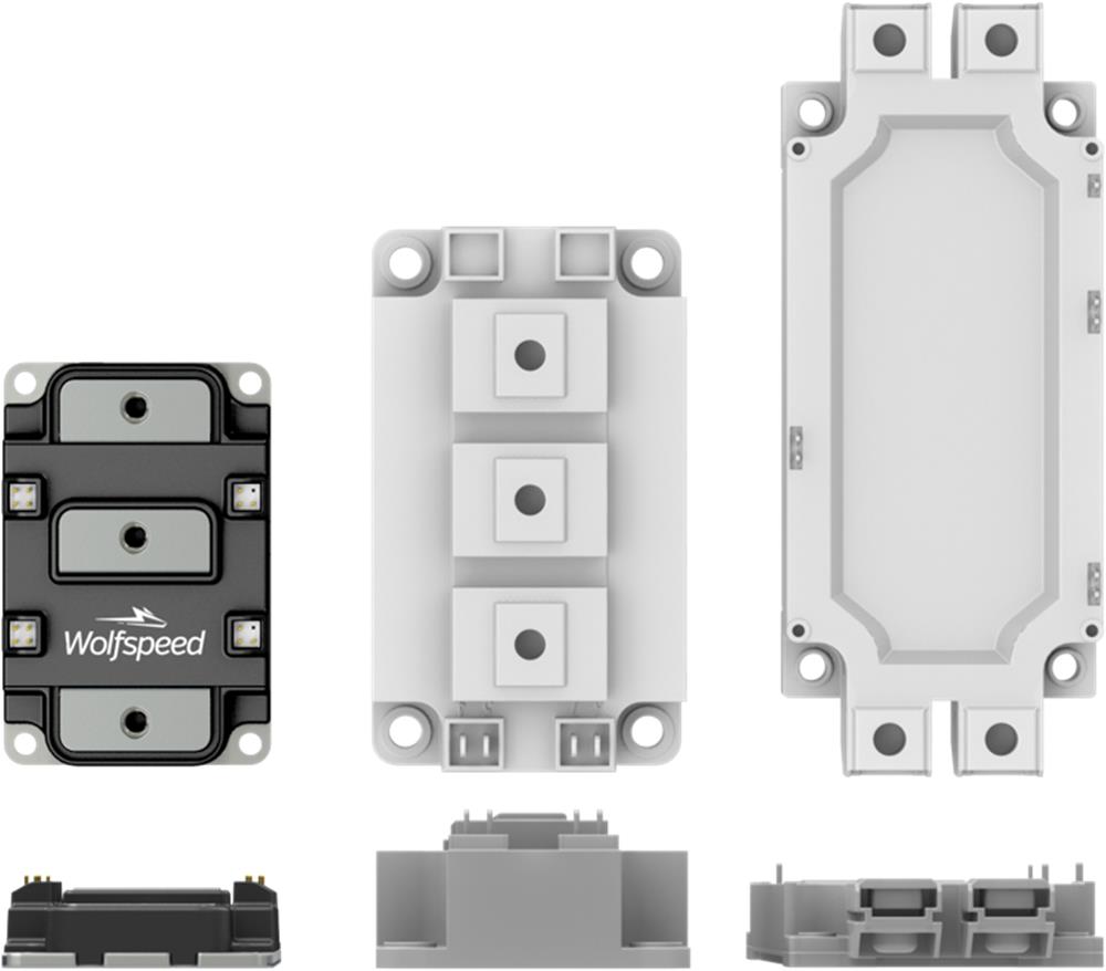
GUID-20230418-SS0I-NCB5-ZZGZ-LG89XDH8X58B-low.jpgFigure 3-5 Size Comparison Between XM3 (Left), 62 mm (Center), and EconoDUAL™(Right)
Table 3-3 XM3 Power Module Part Number Reference
Reference Design Module Part Number
CRD300DA12E-XM3 C4B450M12XM3
CRD250DA12E-XM3 C4B425M12XM3
CRD200DA12E-XM3 C4B400M12XM3