TIDUF23 may 2023
- Description
- Resources
- Features
- Applications
- 5
- 1System Description
- 2System Overview
-
3Hardware, Software, Testing Requirements,
and Test Results
- 3.1 Hardware Requirements
- 3.2 Test Setup
- 3.3 Test Procedure
- 3.4 Test Results
- 4General Texas Instruments High Voltage Evaluation (TI HV EVM) User Safety Guidelines
- 5Design and Documentation Support
- 6Terminology
3.2.1.1 Code Composer Studio Project
To import the software project for TIDM-02014 into CCS, click Project → Import CCS Projects, and browse to <SDK install location>\designs\tidm_02014\<device>\ccs and click Select Folder. Select the project named tidm_02014_<device> and click Finish. The project is now be visible in the Project Explorer pane in CCS. The user's guide provides further details on Importing Projects into CCS.
The folder src_foc includes the typical FOC modules, including park and clarke transforms, PID functions, and estimators. These modules are independent of the specific device and board and are used across several other designs in the SDK.
The folder src_control includes motor drive control files that call motor control core algorithm functions within the interrupt service routines and background tasks. The folder src_sys includes some files reserved for other system features such as drivers for CAN communication. The user can their own code for system control, communication, and so forth. These modules are specific to this reference design project but are independent of the device and board.
Board-specific, motor-specific and device-specific files are in the folder src_board. These files consist of device-specific drivers to run the design. If you want to migrate the project to your own board or other devices, you only need to make changes to the files hal.c, hal.syscfg (or hal_dclinkss.syscfg if used), hal.h, and user_mtr1.h based on the pin assignments and features of your device or board.
 Figure 3-12 Project Explorer View of the
Reference Project
Figure 3-12 Project Explorer View of the
Reference ProjectThe default build configuration for the tidm_02014 project is named F28003x_RELEASE and uses hal.syscfg file to configure the ePWM, CMPSS, and ADC peripherals and the GPIOs. The project's predefined symbols and include the single-shunt current reconstruction library files and function calls as part of the build.
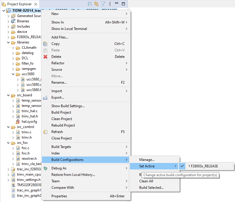
The default build configuration can be modified by right-clicking the project and going to Build Configurations → Manage. Users can add or modify build configurations for different test cases.
 Figure 3-13 Selecting Active Build
Configuration
Figure 3-13 Selecting Active Build
ConfigurationDifferent operational modes of the system can be enabled or disabled using predefined symbols in the project properties. The options are as follows:
- CLOSED_CURRENT_LOOP to
enable closed-loop
control of the d and q axis motor currents.
- CLOSED_SPEED_LOOP to
enable
closed-loop speed control.
Adding these symbols to the predefined symbols list enables the respective functionality. To view and edit the predefined symbols, right-click on your project and select Properties. Then go to the Predefined Symbols section of the C2000 Compiler options as shown in Figure 3-14. By default the above symbols are defined in the pre-defined symbols list and the corresponding features are enabled.
 Figure 3-14 Selecting Predefined Symbols
in the Project Properties