TIDUF26 june 2023 BQ24072 , LMR36520 , TLV62568 , TPS2116
- 1
- Description
- Resources
- Features
- Applications
- 6
- 1System Description
- 2System Overview
-
3Hardware, Software, Testing Requirements,
and Test Results
- 3.1 Hardware Requirements
- 3.2 Test Setup
- 3.3 Test Results
- 4Design and Documentation Support
- 5About the Author
2.2.1 24 VAC to DC Rectification
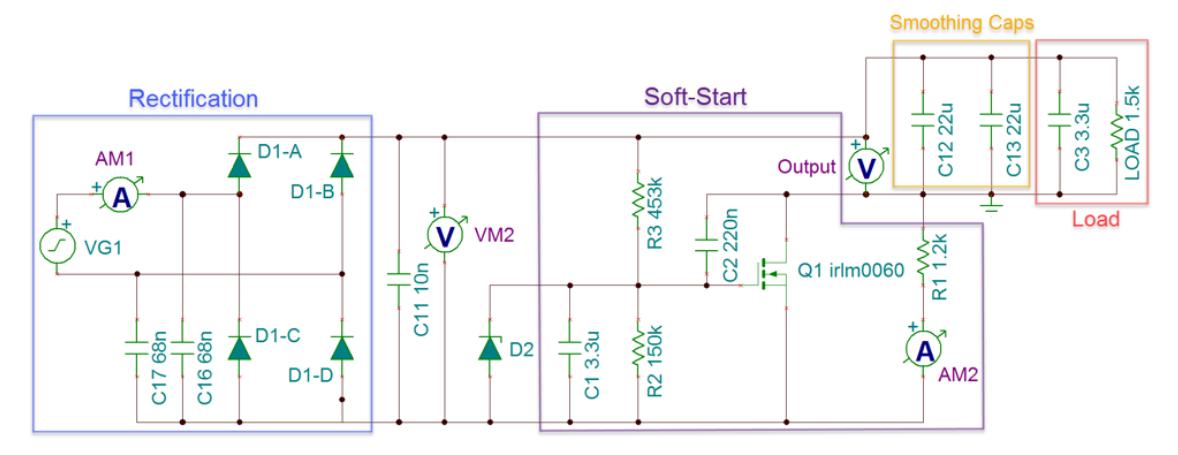
In this design a full-bridge rectifier is used for DC rectification. To prevent a significantly large inrush current during initial connection of 24 VAC, a soft-start circuit is implemented.
The schematic shown in Figure 2-2 shows the rectification and soft-start process. C1, C2, and C3 function as high-frequency bypass capacitors. R1, R2, C4, and C5 provide the soft-start time constant for the gate of the N-channel MOSFET (T1). Q1 has a gate threshold voltage range of 1.0 V to 2.5 V and a 92-mΩ RDS(on)max at VGS = 10 V. The values of R2 and R3 are chosen to voltage divide a maximum of 42 V (the peak of the 24 VAC at the high end of the tolerance) down to approximately 10 V once steady state has been reached. Calculating R2 and R3 is shown in Equation 1.
The Zener diode (D2) is used as a protective device for the MOSFET gate. R4 is used to provide an initial current path while T1 is still open. The use of R4 prevents significantly differing soft-start times due to variances in the 24-VAC transformer and the gate threshold voltage of Q1. The resulting circuit provides a relatively consistent soft-start time regardless of the 24-VAC source variances.
C6 and C7 function as the smoothing capacitors of the rectifier. The TIDA-010932 has a maximum power output of 10 W. The output ripple is a function of the load current. TINA-TI™ simulation shows a maximum worst-case ripple of 11.7 V. That worst-case condition is typically unlikely to occur depending on application; a more reasonable use case of a 100-mA output from the 3.3- V rail and a nominal 24-VAC transformer provides a rectification ripple of approximately 1.4 V. These ripple voltages must be checked in each application. Even at the worse-case scenario as previously outlined, the LMR36520 buck converter is capable of handling those ripple voltages and voltage ranges.
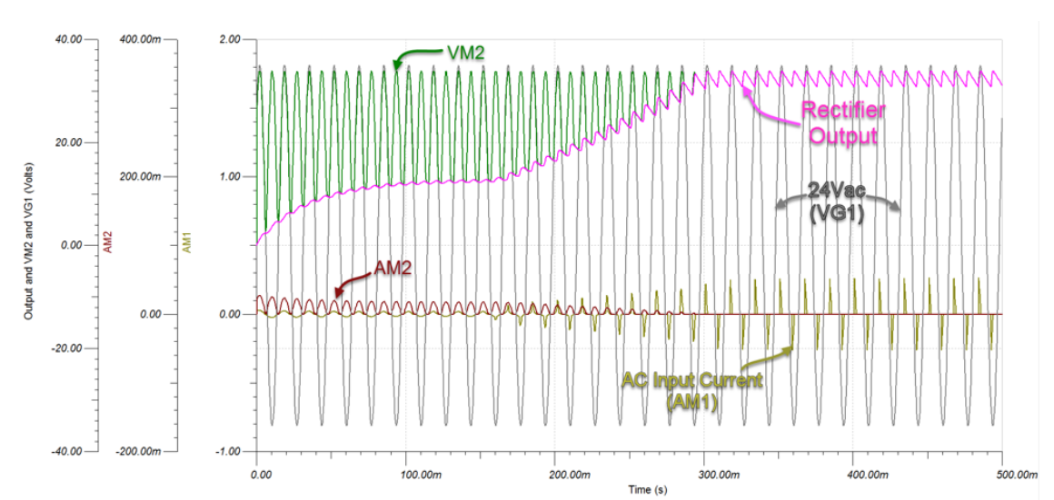
Figure 2-3 shows a simulation example of the schematic detailed in Figure 2-2 under an input power of approximately 750 mW. The time from applied input power to the output of the rectifier reaching steady-state is approximately 300 ms.
 Figure 2-2 Soft-Start Schematic
 Figure 2-3 Soft-Start TINA-TI Simulation
Example