TIDUF26 june 2023 BQ24072 , LMR36520 , TLV62568 , TPS2116
- 1
- Description
- Resources
- Features
- Applications
- 6
- 1System Description
- 2System Overview
-
3Hardware, Software, Testing Requirements,
and Test Results
- 3.1 Hardware Requirements
- 3.2 Test Setup
- 3.3 Test Results
- 4Design and Documentation Support
- 5About the Author
2.2.3.2 USB Power Input
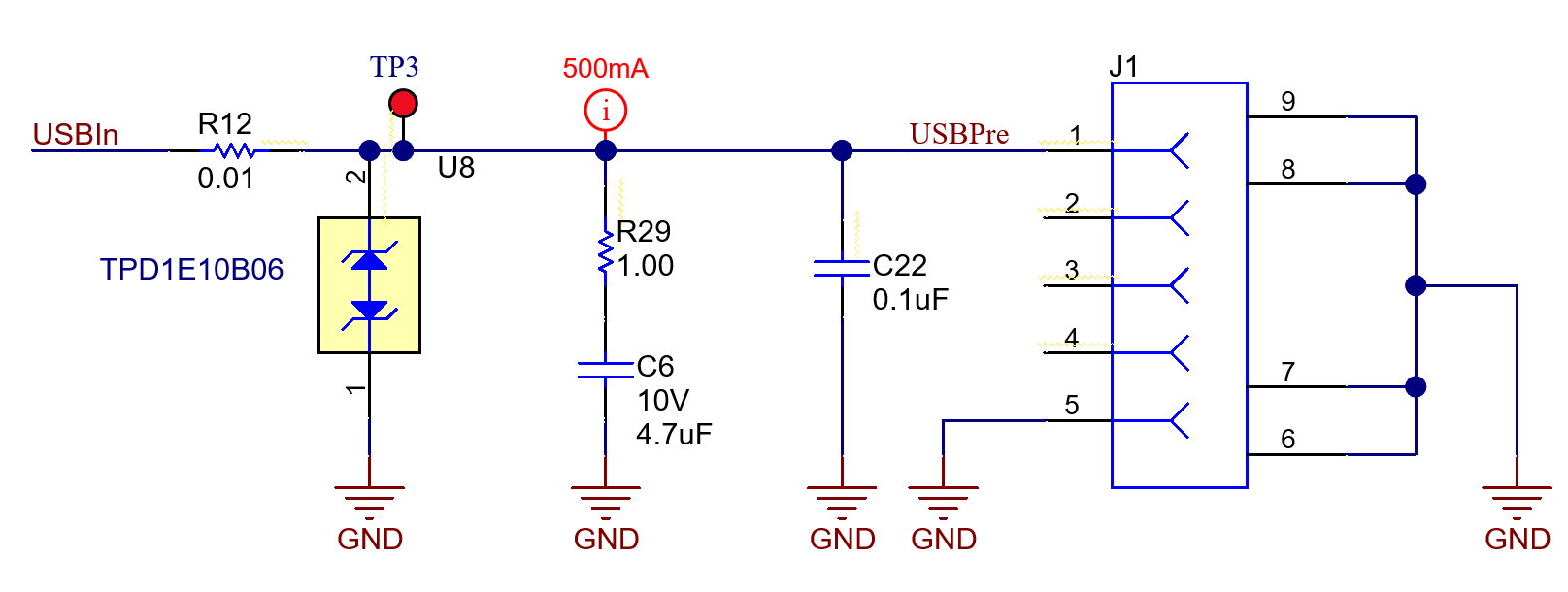
Like the LMR36520 device, the USB power input is capable of powering the entire system. The USB can serve as a backup power source, be used for debugging other aspects of the systems in the product, or be used to charge the battery in case the main 24 VAC is not available. The TIDA-010932 does not supply power to USB; it only sinks power from a USB host. ESD and overvoltage protection are included as shown in Figure 2-6.
 Figure 2-6 USB Implementation
This reference design uses USB 2.0, and therefore assumes the maximum current that can be pulled from a USB host is 500 mA. USB 2.0 specification allows a tolerance of 5% from the nominal 5 V, thereby giving a host voltage range of 4.75 V to 5.25 V. Furthermore, USB 2.0 specification also allows the worst case voltage drop across all cables and connectors to bring the total voltage at load to 4.35 V. The TIDA-010932 is designed to accommodate USB 2.0 at the worst-case specification.
R29 and C6 provide a snubber circuit to the USB Vbus, reducing the overshoot and ringing caused by the cable inductance and capacitive load resonance. The snubber circuit must be tuned for each system design; therefore, the snubber component values used in the TIDA-010932 must be tested when designed into a new system and the values must be changed appropriately.