TIDUF28 November 2023
- 1
- Description
- Resources
- Features
- Applications
- 6
- 1System Description
- 2System Overview
- 3System Design Theory
-
4Hardware, Software, Testing Requirements,
and Test Results
- 4.1 Hardware Requirements
- 4.2 Software Requirements
- 4.3 Test Setup
- 4.4 Test Results
- 5Design and Documentation Support
- 6About the Author
4.3.2 Test Procedure
Use the following steps for the test procedure:
- Become familiar with the TIDA-010255 PCB, schematic and layer plots. Remember that the TIDA-010255 PCB and related interfaces are not isolated.
- Test and validate the TIDA-010255 PCB only in an appropriate lab. Make sure the TIDA-010255 PCB is de-energized and not connected to any power supply.
- Connect either an external MCU or
a C2000 MCU controlCARD to the TIDA-010255 PCB
- External MCU: Interface to connectors J6-J9 and J11.
- C2000 controlCARD: Insert the F28379D controlCARD to the control card connector J1 and J2 on the TIDA-010255 PCB. Be careful inserting to avoid the PCB bends during the insertion.
- When using the F28379D controlCARD, connect an isolated mini-USB adapter from the F28379D controlCARD JTAG connector to the USB interface of the computer.
- Connect a 3-phase motor to terminal J4.
- Connect the low voltage 24-VDC power supply to connector J5. When the power supply is connected to the TIDA-010255 PCB, it draws around 46 mA if the F28379D controlCARD is used.
- Connect the high voltage DC source at terminal J3. The high-voltage ground terminal (-HVDC/GND) is galvanically connected to the ground of the 24-VDC input terminal. Do not turn on the high-voltage DC source, until the corresponding C2000 MCU software or other MCU software is downloaded and running.
- When using the F28379D controlCARD, upload and run the TIDA-010255E2 binary firmware. This is internal test software and not publicly available.
- Turn on the high-voltage DC supply voltage only after the software is running as expected on the selected MCU. Start with 24-V and validate the motor is running as expected. Then the high-voltage DC supply can be increased up to a nominal 320 VDC and absolute maximum 400 VDC. Current limit the high-voltage DC source accordingly to prevent accidental high short circuit current and fire.
- Monitor the surface temperature of the PCB through a thermal camera while operating the board with a load to avoid excess PCB temperatures above 105°C.
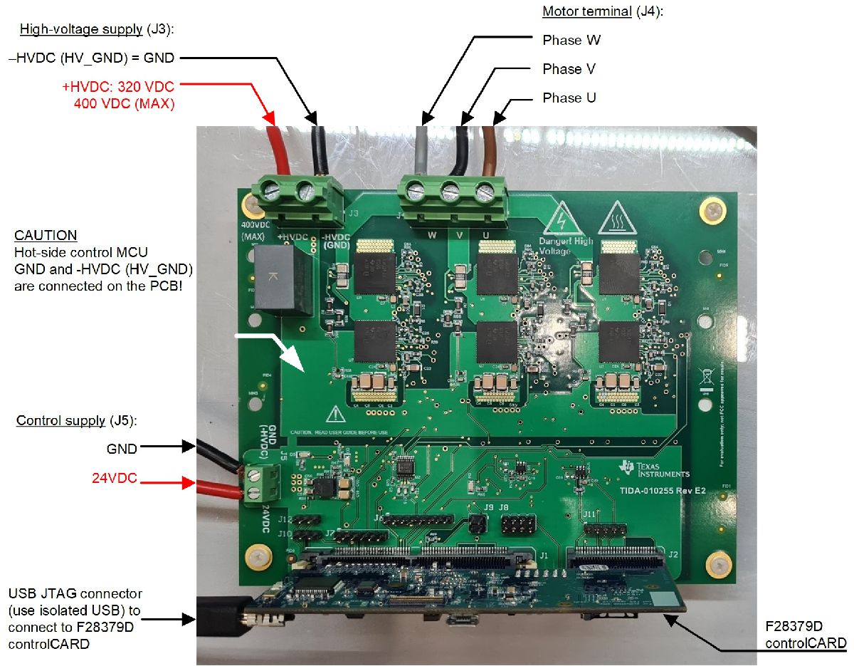
Figure 4-3 shows how the connections are made when using a F28379D C2000 MCU controlCARD. The TIDA-010255 supplies the 5 V required for the C2000 MCU controlCARD, but all interfaces are 3.3 V I/O. The software can then be uploaded to the C2000 MCU through an isolated USB JTAG connector and Code Composer Studio™ software.
 Figure 4-3 TIDA-010255 PCB
Connections
Figure 4-3 TIDA-010255 PCB
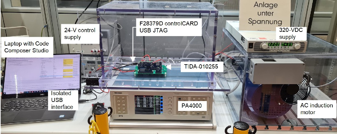
ConnectionsFigure 4-4 shows the test environment for power loss and efficiency measurement with the TIDA-010255 3-phase inverter. Two power supplies are used, a high-voltage 320-VDC supply for the DC-link voltage and a 24-V control supply for the point-of-load supplies. The TMS320F28379D MCU on the F28379D controlCARD is configured through a laptop with Code Composer Studio (CCS) and generates a 3-phase output voltage with variable magnitude and frequency to drive an AC induction motor. The Tektronix PA4000 power analyzer is used to measure the input power, output power and the corresponding TIDA-010255 PCB power losses without a heat sink.
 Figure 4-4 TIDA-010255 Power Loss and
Efficiency Measurement Test Setup