TIDUF31B May   2023  – September 2024


  1.   1
  2.   Description
  3.   Resources
  4.   Features
  5.   Applications
  6.   6
  7. 1System Description
    1. 1.1 Key System Specifications
  8. 2System Overview
    1. 2.1 Block Diagram
    2. 2.2 Design Considerations
    3. 2.3 Highlighted Products
      1. 2.3.1 MSPM0G1507
      2. 2.3.2 UCC28881
      3. 2.3.3 UCC27712
      4. 2.3.4 TLV9064
      5. 2.3.5 TPS54202
  9. 3System Design Theory
    1. 3.1  High-Voltage Buck Auxiliary Power Supply
    2. 3.2  DC Bus Voltage Sensing
    3. 3.3  Motor Drive Stage
    4. 3.4  Bypass Capacitors
    5. 3.5  Phase Current Sensing With Two or Three Shunt Resistors
    6. 3.6  Phase Current Sensing With a Single Shunt Resistor
    7. 3.7  Hall-Effect Sensor or QEI Interface for Sensored Motor Control
    8. 3.8  DAC for Software Debug
    9. 3.9  Overcurrent Protection
    10. 3.10 Overtemperature Protection
    11. 3.11 Isolated UART port
    12. 3.12 Inverter Peak Power Capability
  10. 4Hardware, Software, Testing Requirements, and Test Results
    1. 4.1 Hardware Requirements
      1. 4.1.1 Hardware Board Overview
      2. 4.1.2 Test Equipment for Board Validation
    2. 4.2 Software Requirements
      1. 4.2.1 Getting Started MSPM0 Firmware
        1. 4.2.1.1 Download and Install Software Required for Board Test
        2. 4.2.1.2 Import the Project Into CCS
        3. 4.2.1.3 Compile the Project
        4. 4.2.1.4 Download Image and Spin Motor
    3. 4.3 Test Results
      1. 4.3.1 Test Setup
      2. 4.3.2 Auxiliary Power Supply Test
      3. 4.3.3 Current Open Loop Test
      4. 4.3.4 Overcurrent Protection Test
      5. 4.3.5 Motor Start-Up Sequence
      6. 4.3.6 Load Test
    4. 4.4 Migrate Firmware to a New Hardware Board
      1. 4.4.1 Configure the PWM, CMPSS, and ADC Modules
      2. 4.4.2 Motor and Control Parameters Tuning
  11. 5Design and Documentation Support
    1. 5.1 Design Files
      1. 5.1.1 Schematics
      2. 5.1.2 BOM
    2. 5.2 Tools
    3. 5.3 Documentation Support
    4. 5.4 Support Resources
    5. 5.5 Trademarks
  12. 6About the Author
  13. 7Revision History

Auxiliary Power Supply Test

Figure 4-11 shows the buck power supply waveforms with 200mA load at 15VDC output.

  • CH1 (Blue): 15V voltage rail
  • CH3 (Purple): switching node at pin 1 of UCC28881
  • CH4 (Green): 15V output current

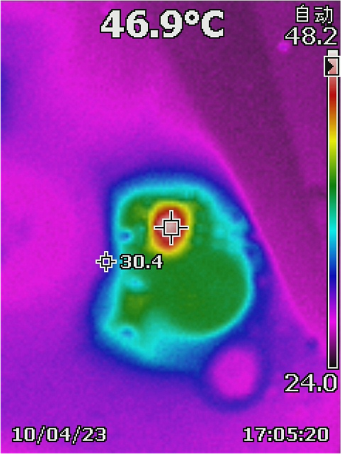
Figure 4-12 shows the buck inductor temperature at 15V, 100mA at 25°C ambient temperature.
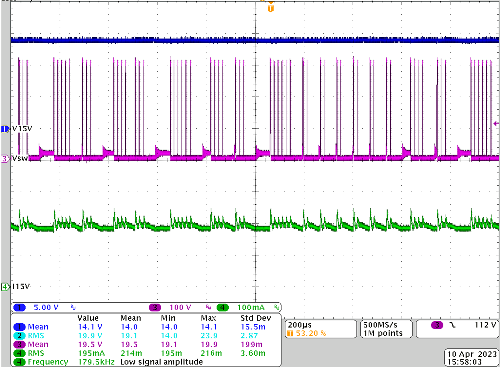
TIDA-010250 UCC28881 Waveform at220VAC, 200mAFigure 4-11 UCC28881 Waveform at
220VAC, 200mA
TIDA-010250 Inductor Temperature
                        Rising of Buck Supply at 220VAC, 100mAFigure 4-12 Inductor Temperature Rising of Buck Supply at 220VAC, 100mA