TIDUF41A October 2023 – June 2024
3.1 Hardware Requirements
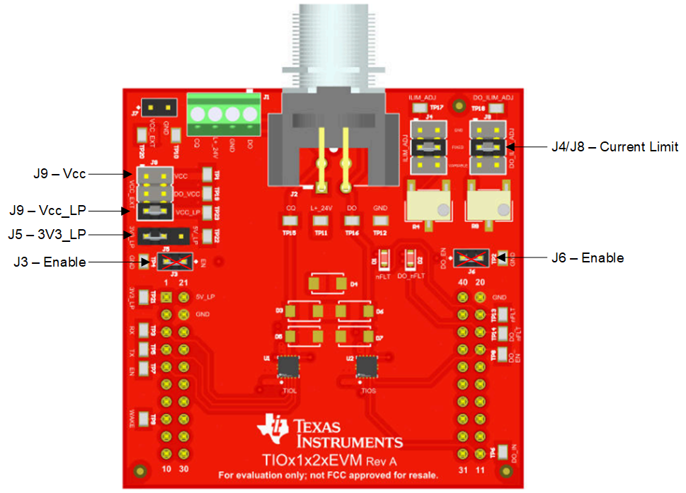
To get the TIOx1x2x EVM working for IO-Link on the MSPM0 LaunchPad Development Kit, make sure to set the jumpers correctly. Use Figure 3-1 as a guideline.

Figure 3-1 TIOx1x2xEVM Jumper Settings
To be able to control the TIOLs enable line, remove J3; otherwise, the IO-Link stack is not able to control the enable line and therefore the TIOL112 driver. The driver is not damaged, but causes a fault.
Also J6 must be removed, this is the enable line of the additional digital output device. The reason behind this change is not about enabling the device, but this line is shared with the SWDIO, so one of the debug lines. Pulling this line to GND with this jumper prevents debugging the microcontroller.
J9 and J5 control the power supply. As long as the TIOx1x2xEVM is not modified (and assembled with TIOL1123), always set J5 to 3V3_LP. J9 allows control of where the design is powered from. With a jumper on Vcc_LP, the LaunchPad Development Kit needs a dedicated power supply. To power the LaunchPad from the L+ line and the linear regulator inside the TIOL1123, also set a jumper on VCC.
| JUMPER | CONFIGURATION | COMMENT |
|---|---|---|
| J3 | Remove | TIOL112 Enable line |
| J4 | Set to fixed | TIOL112 Current limit |
| J5 | Set to 3V3_LP | Power supply selection |
| J6 | Remove | TIOS102 Enable line |
| J8 | Don't care | TIOS102 Current limit |
| J9 | Short Vcc_Lp and VCC | Power supply selection |

Figure 3-2 Jumper Settings VCC
For further details refer to the TIOx1x2x EVM User's Guide.
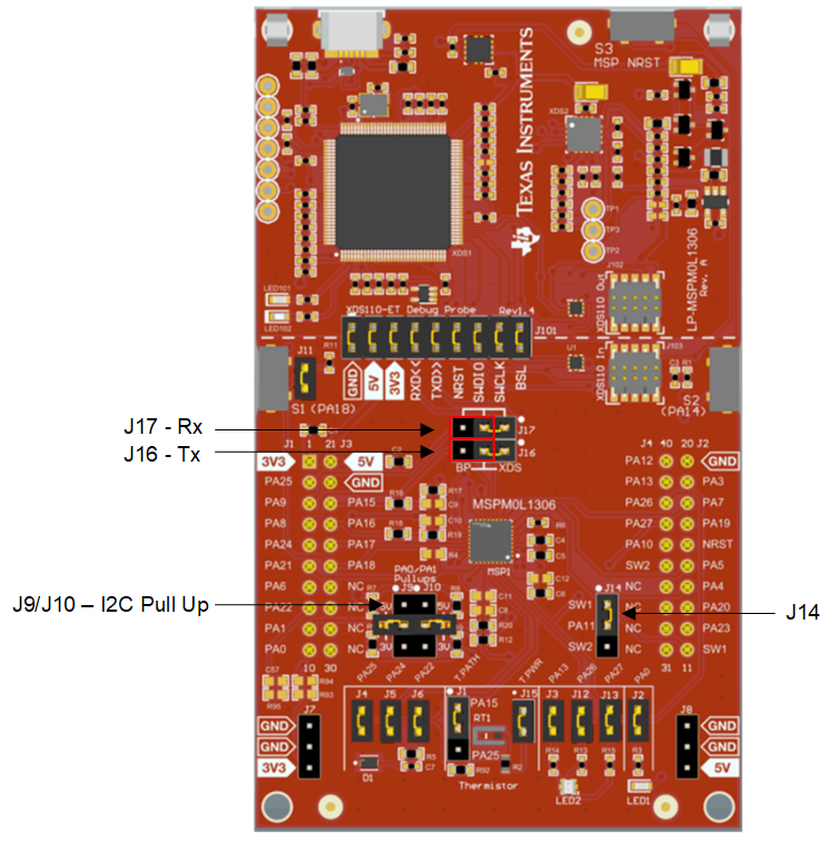
Besides the previously-mentioned proper configuration, for proper communication, the MSPM0L1306 must be configured correctly. Figure 3-3 shows the MSPM0L1306 LaunchPad™ Development Kit jumper settings. The default configuration of J16 and J17 must be changed as shown.

Figure 3-3 MSPM0L1306 LaunchPad™ Development Kit Jumper Settings
| JUMPER | CONFIGURATION | COMMENT |
|---|---|---|
| J9 and J10 | Open or 2-3 | Configures a pullup for I2C pins. If an external I2C EEPROM is used, set to 2-3. |
| J14 | 1-2 | |
| J16 and J17 | 2-3 | Configures the UART signals to the BoosterPack headers. |