TIDUF41A October 2023 – June 2024
3.2 Test Setup
To test the TIDA-010263, prepare the two boards as previously described and stack together. The supplied hex file can now be loaded to the MSPM0L1306 device using Code Composer Studio (CCS) or UniFlash.
The UniFlash webpage allows you to scan for connected devices and lists the LP-MSPMO1306. Click on the Start button below the device.
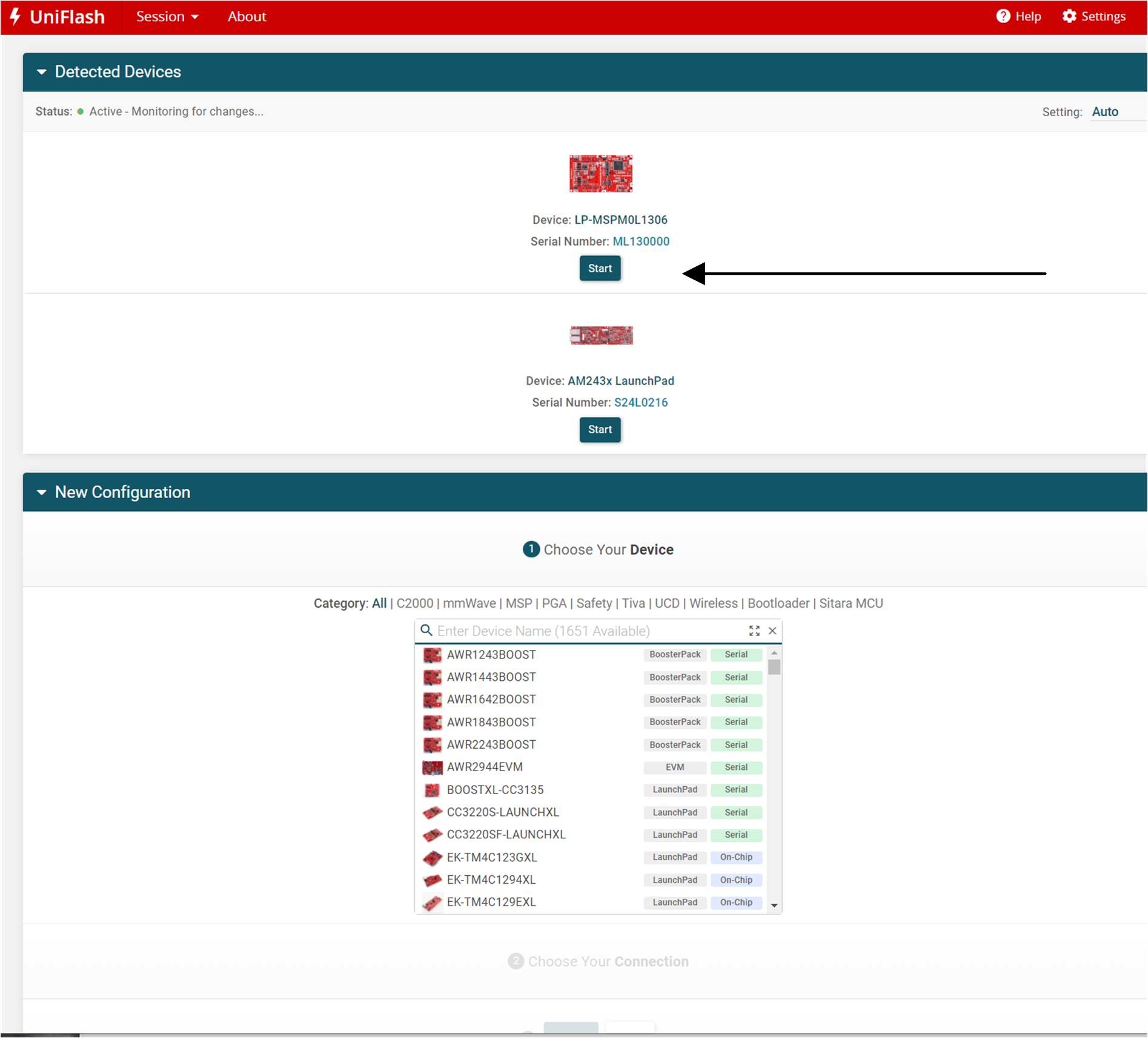
Figure 3-4 UniFlash Start
A screen like Figure 3-5 appears, click the Browser button and select the hex file.
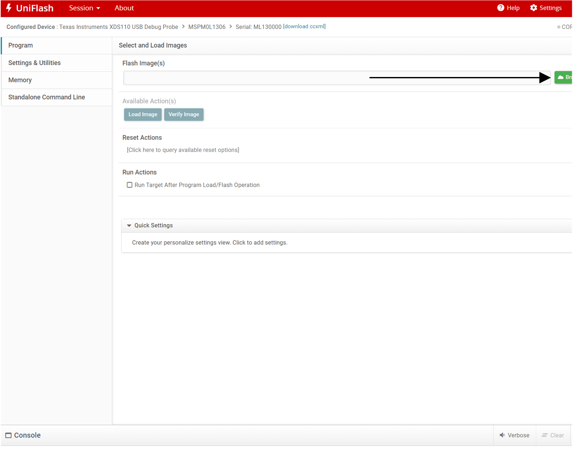
Figure 3-5 UniFlash Select Image
By clicking the Load Image button, the hex file is loaded on the MSPM0 device. The debugger is possibly required to allow a firmware update. If this is needed, an additional prompt appears.
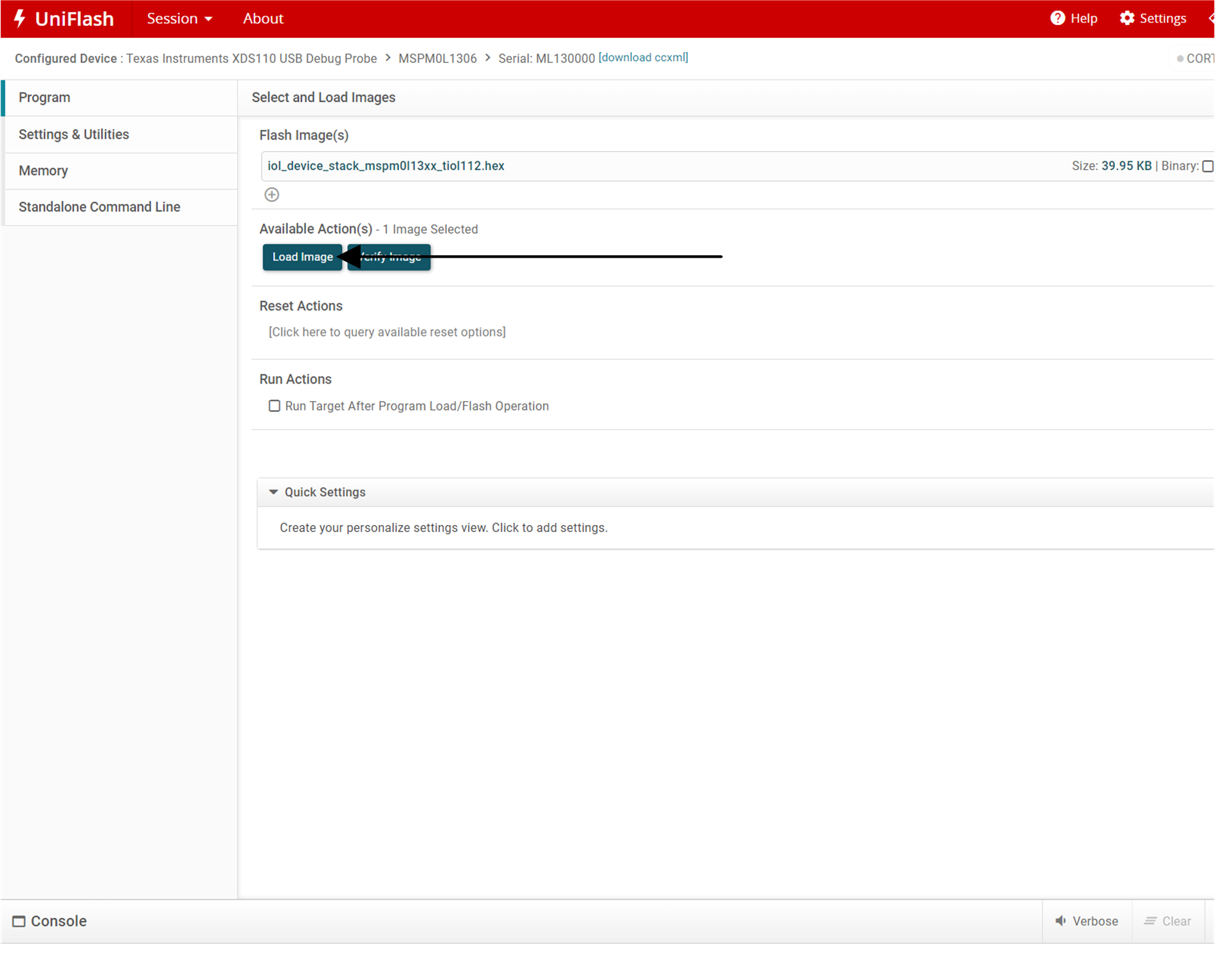
Figure 3-6 UniFlash Flash Image
After the MSPM0L1306 is programmed, the USB connection can be disconnected and TIDA-010263 can be connected to an IO-Link Master, such as TIDA-010234.
To test the reference design, connect TIDA-010234 as shown in Figure 3-7. An IO-Link communication with COM3 and 400µs can be initiated and the timings can be measured.

Figure 3-7 Test Setup
The software running on MSPM0L1306 can now enable an IO-Link communication with COM3 and up to 400µs cycle time. The device sends 16 bits of input process data, 8-bit brightness information from a light sensor, and 8-bit temperature information. The device does not accept any output process data.
The RGB LED that is part of the MSPM0L1306 LaunchPad can be controlled through the last 3 bits of the 8-bit indexed service data unit (ISDU) with index 65.
To connect TIDA-010234 to TIDA-010263, start the supplied IOL Master GUI and scan for a connected Master (see Figure 3-8).
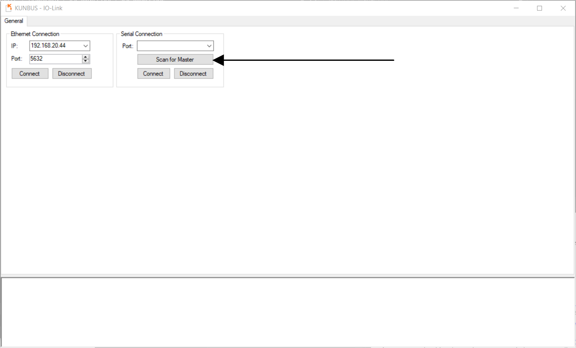
Figure 3-8 TIDA-010234 Search Master
As Figure 3-9 shows, the serial port of the connected Master appears in the Port: drop-down menu. Click the Connect button to connect to the port.
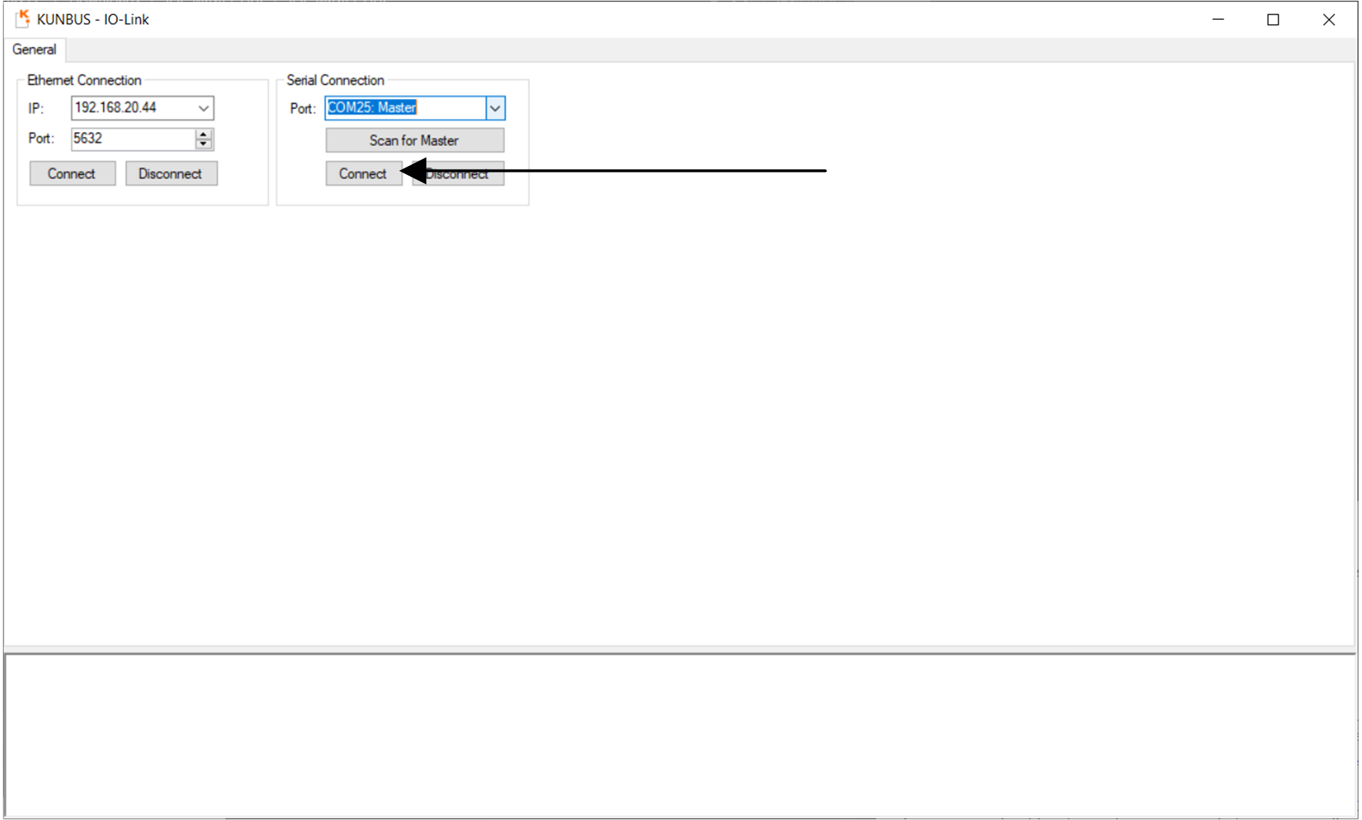
Figure 3-9 TIDA-010234 Connect Master
Figure 3-10 shows where to select the Std Port Config tab. Select this tab and configure the port where TIDA-010263 is connected. To do so leave the default settings and click the Set Port Config tab.
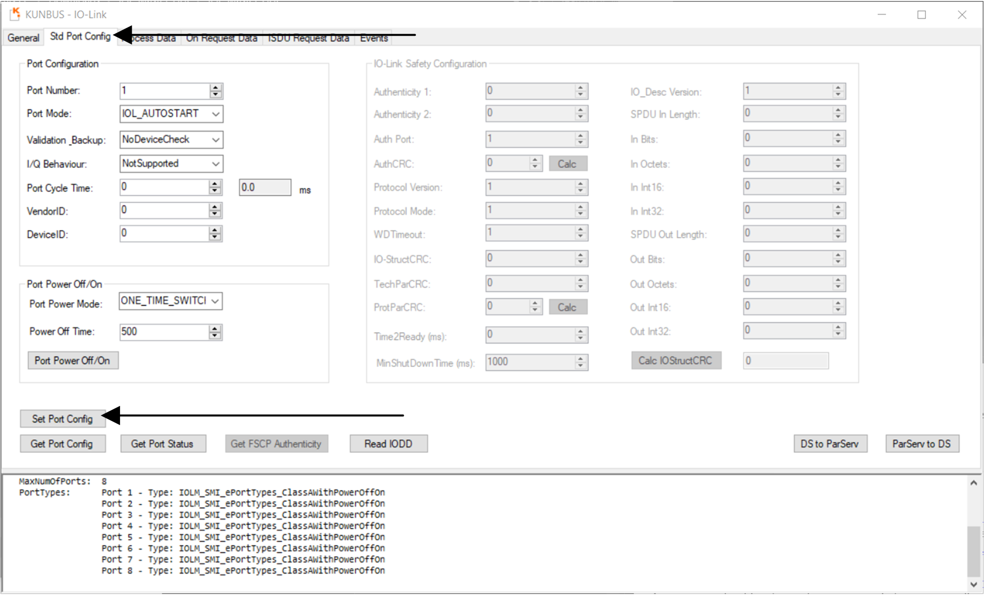
Figure 3-10 TIDA-010234 Configure Port
The IO-Link Master can now establish a connection in COM3 with a 400µs cycle time. This can be verified, by clicking the Get Port Status button (see Figure 3-11). The established transmission rate and cycle time appears in the lower tab of the GUI.
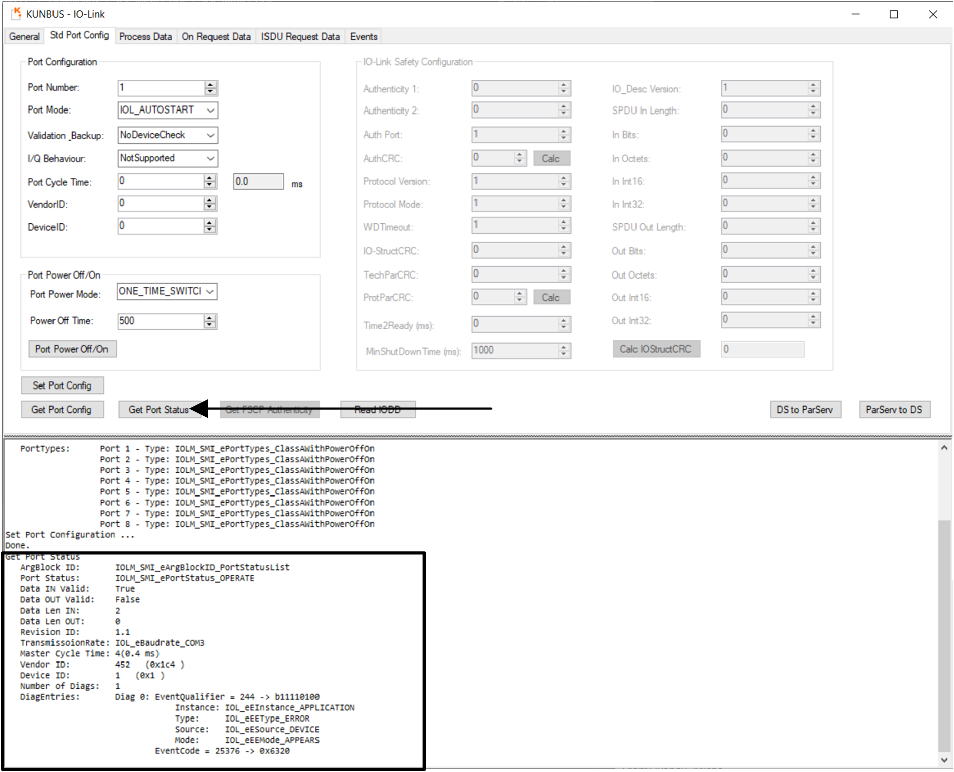
Figure 3-11 TIDA-010234 Port Status
Data can now be read and written. To read process data, switch to the Process Data tab and select the Read button.
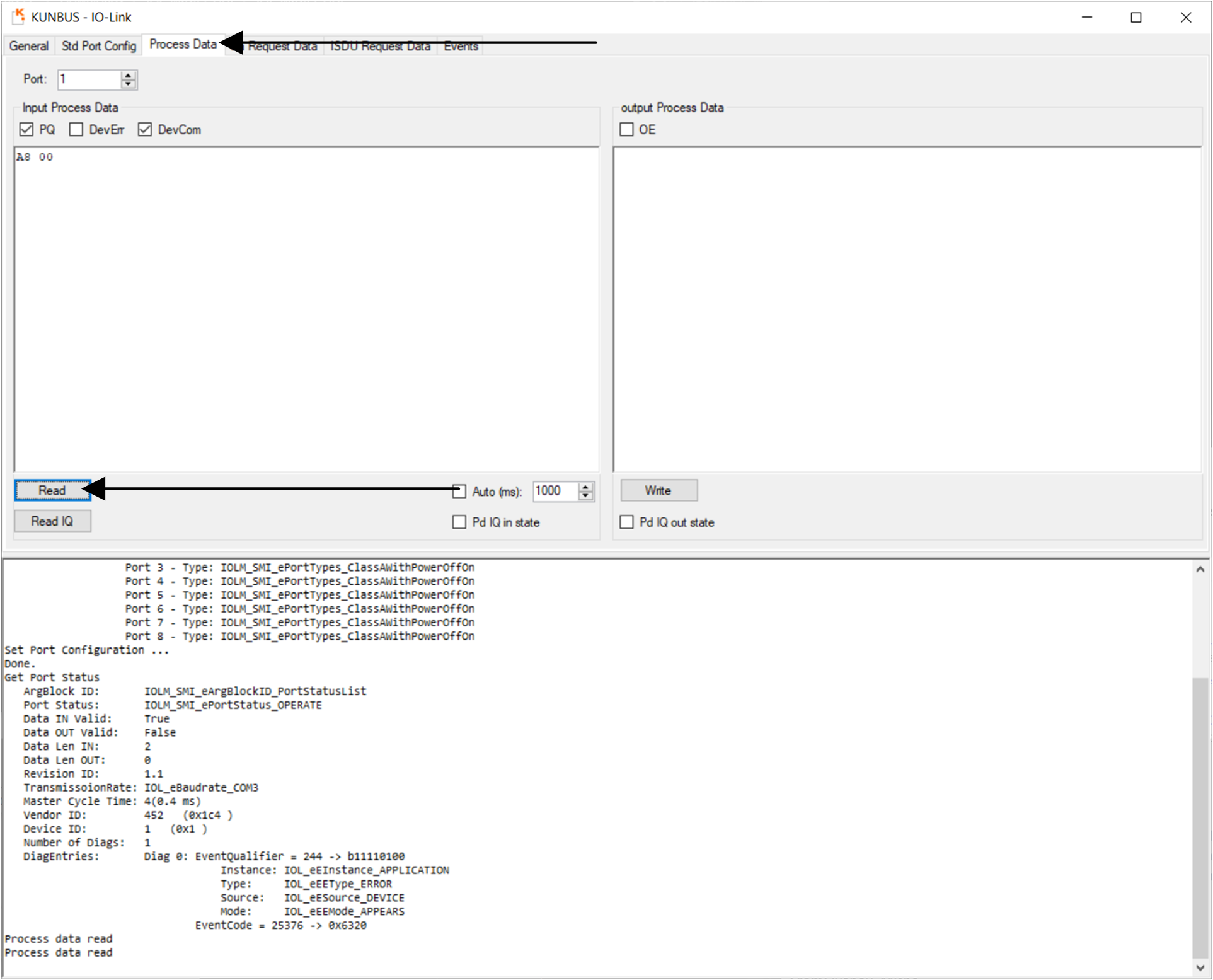
Figure 3-12 TIDA-010234 Process Data
In a similar manner, on request data can be read and written. As illustrated in Figure 3-13, select the On Request Data tab, enter the index to read or write (in this example 65 for the RGB LED) and click the Read button to read the data. For writing, enter the value to write in the box and click the Write button. The example value 02 turns on D5 of the LaunchPad in green.
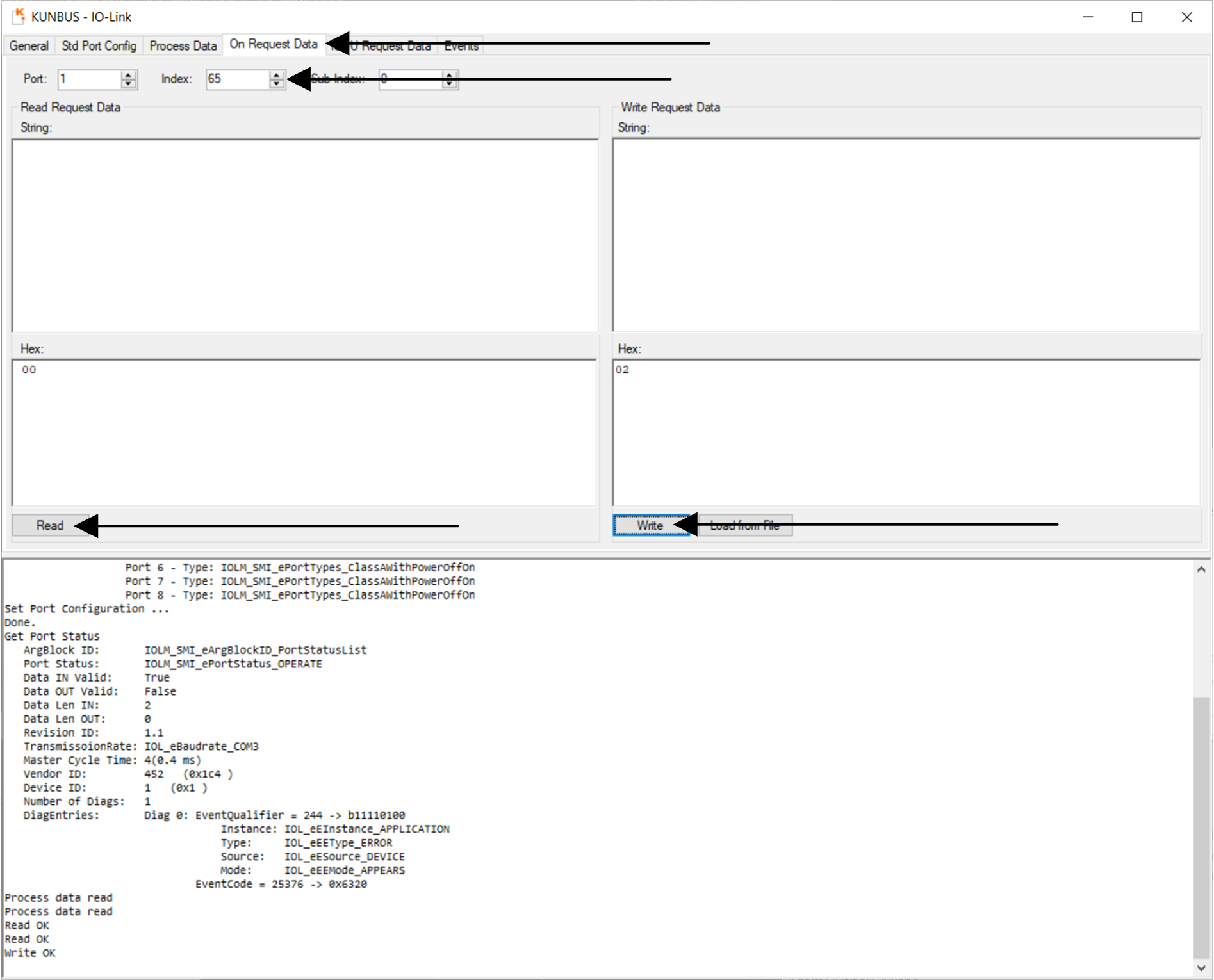
Figure 3-13 TIDA-010234 On Request Data