TIDUF41A October   2023  – June 2024


  1.   1
  2.   Description
  3.   Resources
  4.   Features
  5.   Applications
  6.   6
  7. 1System Description
    1. 1.1 Key System Specifications
  8. 2System Overview
    1. 2.1 Block Diagram
    2. 2.2 Design Considerations
    3. 2.3 Highlighted Products
      1. 2.3.1 TIOL112
      2. 2.3.2 MSPM0L1306
  9. 3Hardware, Testing Requirements, and Test Results
    1. 3.1 Hardware Requirements
    2. 3.2 Test Setup
    3. 3.3 Test Results
      1. 3.3.1 TCD_PHYL_INTF_TRENHIGH and TCD_PHYL_INTF_TRENLOW
      2. 3.3.2 TCD_PHYL_INTF_UARTTRANSDELAY
      3. 3.3.3 TCD_PHYL_INTF_RESPONSETIME
      4. 3.3.4 TCD_PHYL_INTF_ISIRD
  10. 4Design and Documentation Support
    1. 4.1 Design Files
      1. 4.1.1 Schematics
      2. 4.1.2 BOM
    2. 4.2 Tools and Software
    3. 4.3 Documentation Support
    4. 4.4 Support Resources
    5. 4.5 Trademarks
  11. 5About the Author
  12. 6Revision History

TCD_PHYL_INTF_RESPONSETIME

To measure tA, the time between the start bit of the last master message and the start bit of the response from the device is measured. The time of the last message from the master is subtracted. The time is allowed to be between 1 and 10 times the bit time. For COM3 this allows 4.34µs and 43.4µs.
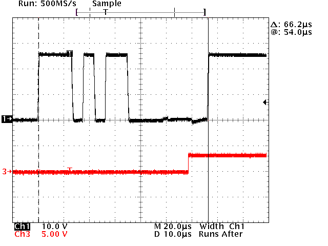
TIDA-010263 TA Measurement, Master Start
                    Bit Transition to Device Start Bit Transition
Black = C/Q Line, Red = TIOL112 enable signal
Figure 3-20 TA Measurement, Master Start Bit Transition to Device Start Bit Transition
Equation 2. 66.2µs – 11 × 4.34µs = 18.46µs, this equals 4.25 TBIT

The measured time is within the limits.