TIDUF42 January 2024
3 System Design
R5F_0_1 Initialization
Use the following steps to initialize R5F_0_0 for motor 1 (single_chip_servo_remote_core_start):
- Set up GPIO pin direction and initial values (init_gpio_state)
- Disable EPWM (enable_pwm_buffers)
- Set up EPWM frequency and interrupt for motor 1 (init_pwms)
- Set up ICSSG0 PRU1 for EnDAT 2.2 motor 1 (channel 0, init_encoder)
- Configure g_mux_en to 1 in ICSSG_SA_MX_REG Register. HW_WR_REG32((CSL_PRU_ICSSG0_PR1_CFG_SLV_BASE+0x40), (0x80))
- Register & enable ICSSG EnDat PRU FW interrupt
-
- Interrupt number: ICSSG_PRU_ENDAT_INT_NUM
- Callback function: pruEncoderIrqHandler
- Set up the EnDat 2.2 parameters
- gEndat_multi_ch_mask = ENDAT_MULTI_CH0 | ENDAT_MULTI_CH2;
- gEndat_is_multi_ch = CONFIG_ENDAT0_MODE & 1;
- gEndat_is_load_share_mode = CONFIG_ENDAT0_MODE & 2;
- Initialize ICSSG0 PRU1 (endat_pruss_init)
- Initialize the encoder using the encoder driver API (endat_init)
- Configure the encoder using the encoder driver API (endat_config_multi_channel_mask)
- Configure Delays based on the ICSSG frequency
- Load and run the EnDat 2.2 PRU FW to ICSSG0 PRU1 (endat_pruss_load_run_fw)
- Check initialization ack from firmware, with a timeout of 5 second (endat_wait_initialization)
- Set default frequency to 16 MHz for 2.2 encoders (endat_init_clock)
- Set propagation delay to make 16 MHz work at 300-MHz PRU (endat_handle_prop_delay(priv, 265))
- SetsEnDat 2.2 FW to periodic triggering (endat_config_periodic_trigger)
- Configures parameters for EnDat 2.2
FW periodic mode (endat_config_periodic_mode)
- IEP0 CMP3 event for channel 0 (3000ns from start of PWM period)
- IEP0 CMP6 event for channel 2 (3000ns from start of PWM period)
- Start receiving EnData 2.2 data (endat_handle_rx)
- Set up ICSSG0 PRU0 for SDFM for motor 1 (init_sddf)
- Initialize IEP0, configure SYNC0 SD clock (init_IEP0_SYNC)
- Initialize ICSSG0 PRU0 (initIcss)
- Register and enable ICSSG SDFM RTU FW
interrupt
- Interrupt number: ICSSG_RTU_SDDF_INT_NUM
- Callback function: rtuSddfIrqHandler
- Initialize RTU/PRU core for SDFM
(initPruSddf)
- RTU sample base address: gTestSdfmPrms.samplesBaseAddress
- PRU sample base address: gTestSdfmPrms.samplesBaseAddress+0x80
- Start IEP0 (start_IEP0)
- Force SW sync for EPWM0. Other PWMs are synchronized through hardware sync daisy-chain (EPWM_tbTriggerSwSync)
- Disable the EPWM output buffer (enable_pwm_buffers)
- Initialize the parameters for FOC (init_pids)
- Enable the EPWM output buffers for motor 1 (enable_pwm_buffers(TRUE))
R5F_0_1 Initialization
Use the following steps to initialize R5F_0_1 for motor 2 (single_chip_servo_remote_core_start):
- Set up EPWM frequency and interrupt (init_pwms) for motor 2
- Register and enable ICSSG EnDat PRU FW interrupt for motor 2
- Interrupt number: ICSSG_PRU_ENDAT_INT_NUM+2
- Callback function: pruEncoderIrqHandler2
- Register & enable ICSSG SDFM PRU FW interrupt for motor 2
- Interrupt number: ICSSG_PRU_SDDF_INT_NUM
- Callback function: pruSddfIrqHandler
- Initialize the parameters for FOC (init_pids)
Set up Interrupts
Use the following instructions to set the Interrupts and Handlers:
EPWM interrupt (50 kHz), ISR - App_epwmIntrISR (Motor 1) or App_epwmIntrISR2 (Motor 2)
- Clear the EPWM interrupt
SDFM interrupts (50 kHz), ISR - rtuSddfIrqHandler (Motor 1) or pruSddfIrqHandler (Motor 2)
- From sample 8192 to 16384, compute the SDFM channel offsets (0–2 or 3–5). The SDFM channel offsets are used in the FOC loop when PRECOMPUTE_LEVEL == NO_PRECOMPUTE
- At sample 16384, write EPWM for Phase A, Phase B, and Phase C to lock the rotor to electrical 0 and disable SDFM interrupts
- Clear interrupt at source
EnDAT 2.2 interrupt (50 kHz), ISR – pruEncoderIrqHandler (for Motor 1)
- Clear interrupt at source
- For sample 0 – 8192 doing nothing
- For sample 8193–16383:
- Calculate mechanical and electrical angle offset (localEnDatGetSingleMulti)
- For sample 16384:
- Find the average of the mechanical and electrical angle offset
- Turn off all phases
- Save the mechanical and electrical angle offset
- For sample after 16384:
- Start FOC loop and unlock the rotor
- Get the latest mechanical theta and multiturn position from the encoder (localEnDatGetSingleMulti)
- Use calculated offset from electrical 0, 4 pole pairs
- Running FOC loop to compute the space vector
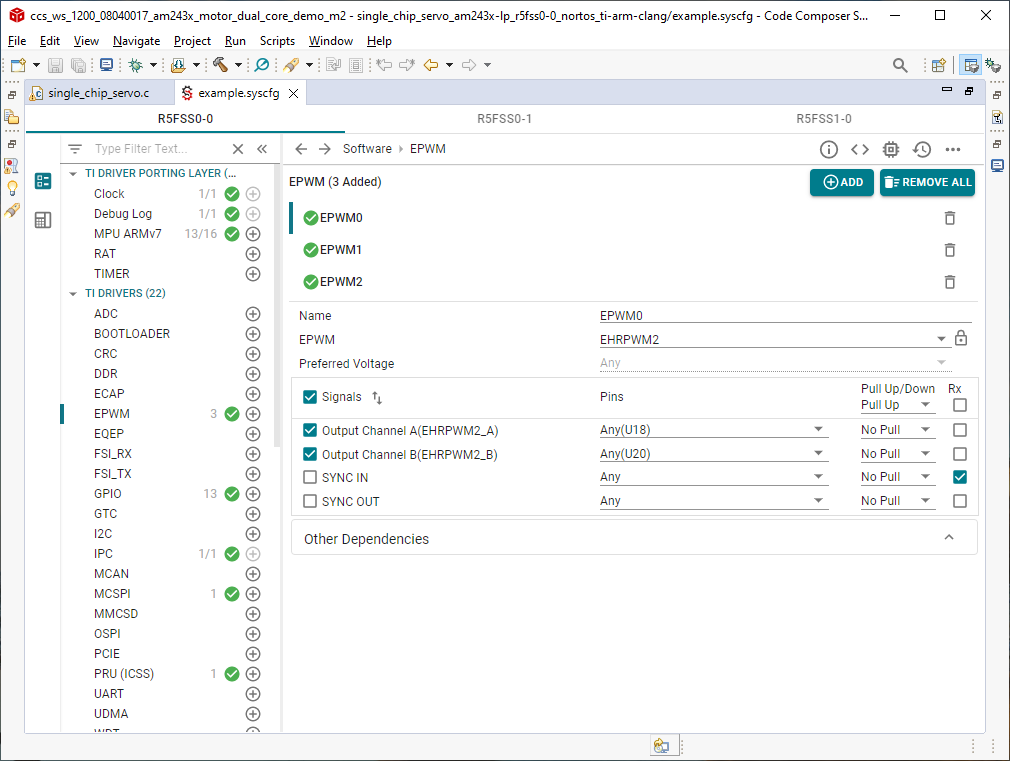
- Write next CMPA values. Swap cmp0 and cmp2 because the HW connect EPWM0 to Phase C and EPWM2 to Phase A
- EPWM0 is actually uses EHRPWM2; EPWM1 is using EHRPWM1 and EPWM2 is using EHRPWM0
- See the EPWM settings in
example_syscfg of single_chip_servo_am243x-lp_r5fss0-0_nortos_ti-arm-clang for
details
 Figure 3-1 EPWM Settings for Motor
1
EnDAT 2.2 interrupt (50 kHz), ISR – pruEncoderIrqHandler (for Motor 2)
- Clear interrupt at source
- For sample 0–8192 doing nothing
- For sample 8193–16383:
- Calculate mechanical and electrical angle offset (localEnDatGetSingleMulti)
- For sample 16384:
- Find the average of the mechanical and electrical angle offset
- Turn off all phases
- Save the mechanical and electrical angle offset
- For sample after 16384:
- Start FOC loop and unlock the rotor
- Get the latest mechanical theta and multi-turn position from the encoder (localEnDatGetSingleMulti)
- Use calculated offset from electrical 0, 4 pole pairs
- Running FOC loop to compute the space vector
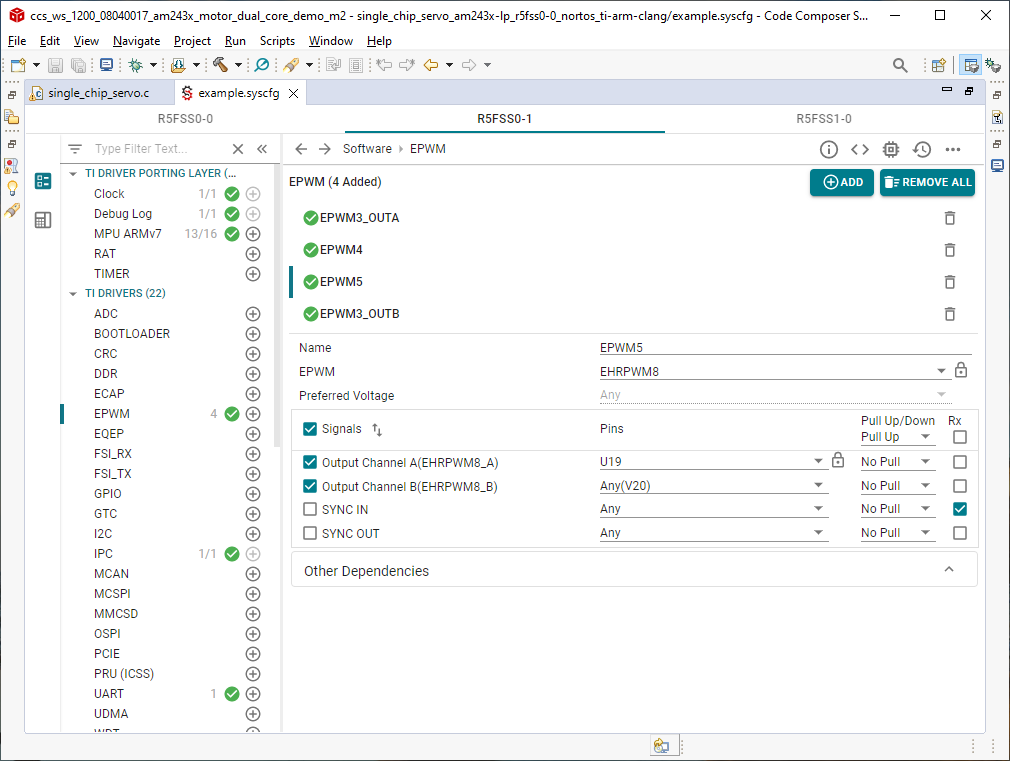
- Write next CMPA values. Swap cmp0 and cmp2 because the HW connect EPWM0 to Phase C and EPWM5 to Phase A
- EPWM0 is actually uses EHRPWM5; EPWM1 is using EHRPWM4 and EPWM2 is using EHRPWM3
- See the EPWM settings in
example_syscfg of single_chip_servo_am243x-lp_r5fss0-1_nortos_ti-arm-clang for
details
 Figure 3-2 EPWM Settings for Motor
2