TIDUF43 August 2024
- 1
- Description
- Resources
- Features
- Applications
- 6
- 1System Description
- 2System Overview
- 3System Design Theory
- 4Hardware, Software, Testing Requirements, and Test Results
- 5Design and Documentation Support
- 6About the Author
4.4.1 State Transition
The test setup for state transitions between low-power mode and active mode involve emulating a simple vehicle ECU with a LM53625xQEVM buck converter and a 150W electronic load configured in constant-current mode.
 Figure 4-2 State Transition Test Block Diagram
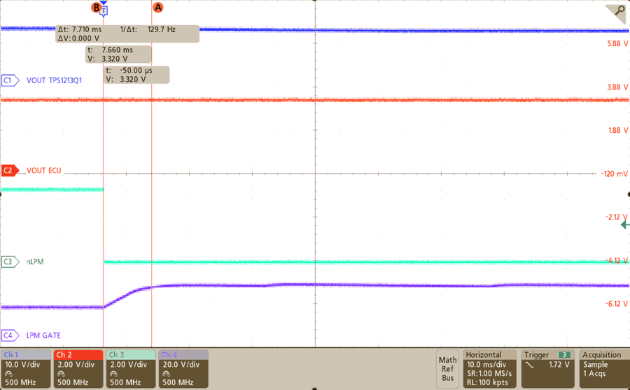
Figure 4-3 Active to Low-Power Mode
In Figure 4-3, the test begins by pressing S3 to trigger the MSPM0L1306-Q1 to transition the system to low-power mode. In this state, nLPM and INP are both pulled low, signaling the TPS1213-Q1 to drive the low power path instead of the main path.

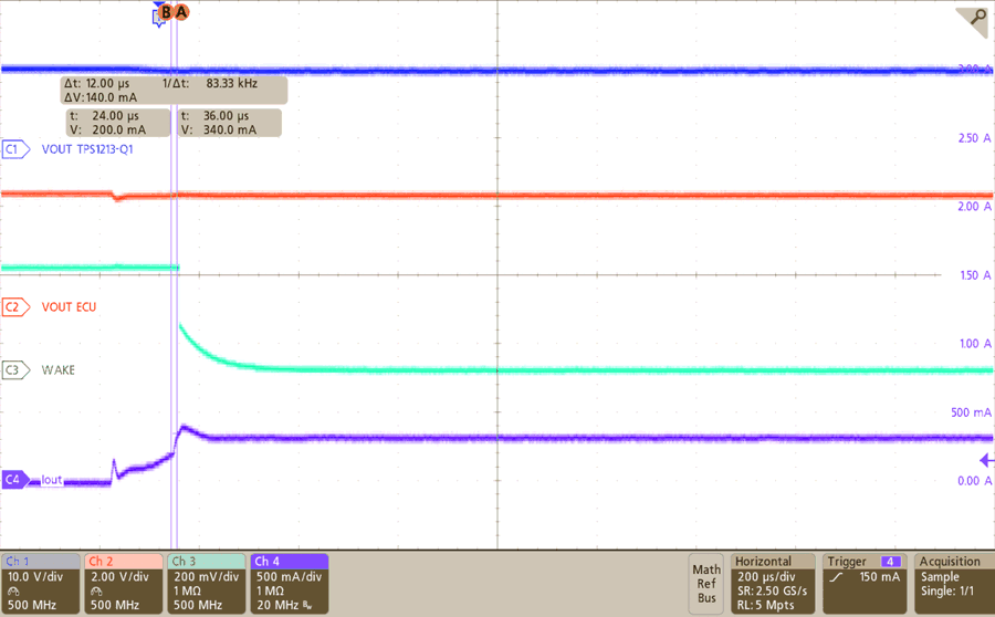
Figure 4-4 Automatic-Load Wakeup
In Figure 4-4, the system is in low-power mode initially, but the electronic load is turned up to cross the automatic load wakeup threshold at 200mA. The TPS1213-Q1 automatically transitions from using the low power path to main path in < 12μs. Concurrently, the WAKE signal asserts low to alert the MSPM0L1306-Q1 to transition the whole system to active mode.