TIDUF43 August   2024


  1.   1
  2.   Description
  3.   Resources
  4.   Features
  5.   Applications
  6.   6
  7. 1System Description
    1. 1.1 Terminology
    2. 1.2 Key System Specifications
  8. 2System Overview
    1. 2.1 Block Diagram
    2. 2.2 Design Considerations
    3. 2.3 Highlighted Products
      1. 2.3.1 TPS1213-Q1 45V, Low IQ, Automotive High-Side Switch Controller With Low-Power Mode and Adjustable Load Wakeup Trigger
      2. 2.3.2 INA296x-Q1 AEC-Q100, –5V to 110V, Bidirectional, 1.1MHz, 8V/μs, Ultra-Precise Current-Sense Amplifier
  9. 3System Design Theory
    1. 3.1 Low-Power Mode Considerations
    2. 3.2 Precharge Circuit Considerations
    3. 3.3 Short-Circuit Protection
    4. 3.4 LM74704-Q1 Enable
    5. 3.5 Headers
      1. 3.5.1 Headers for Configuring INA296B-Q1
      2. 3.5.2 Headers for Configuring TPS1213-Q1
    6. 3.6 Software Considerations
      1. 3.6.1 Fuse Channel Definition
      2. 3.6.2 Software Functions
    7. 3.7 Optional Output TVS Diode
  10. 4Hardware, Software, Testing Requirements, and Test Results
    1. 4.1 Hardware Requirements
    2. 4.2 Software
    3. 4.3 Test Setup
    4. 4.4 Test Results
      1. 4.4.1 State Transition
      2. 4.4.2 System IQ in Low-Power Mode
      3. 4.4.3 Precharge Test
      4. 4.4.4 Overcurrent Protection
      5. 4.4.5 PWM Overcurrent
      6. 4.4.6 Short-Circuit Protection
      7. 4.4.7 Thermal Testing
      8. 4.4.8 CISPR-25 Emissions Testing
        1. 4.4.8.1 Conducted Emissions Testing
        2. 4.4.8.2 Radiated Emissions Testing
        3. 4.4.8.3 Summary of Results
  11. 5Design and Documentation Support
    1. 5.1 Design Files
      1. 5.1.1 Schematics
      2. 5.1.2 BOM
      3. 5.1.3 PCB Layout Recommendations
        1. 5.1.3.1 Layout Prints
      4. 5.1.4 Altium Project
      5. 5.1.5 Gerber Files
      6. 5.1.6 Assembly Drawings
    2. 5.2 Documentation Support
    3. 5.3 Support Resources
    4. 5.4 Trademarks
  12. 6About the Author

Short-Circuit Protection

For this test, the electronic load was turned on initially at 5A and set to constant resistance mode. Then, the "short" option was clicked on the electronic load to initiate a short-circuit event in the TPS1213-Q1. As shown in Figure 4-14, the current spikes up to about 85A before the TPS1213-Q1 turns off the main gate in less than 6μs. In this state, nFLT asserts low and the main gate remains latched off until S2 or S3 are pressed, which signals the MSPM0L1306-Q1 to toggle INP to attempt to clear the latch. If the latch is successfully cleared, nFLT asserts high and alerts the MCU that the fault has been cleared. Figure 4-15 shows an example of successfully recovering from a short-circuit event.
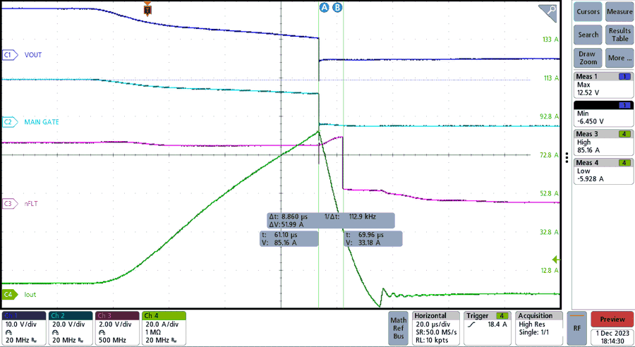
TIDA-020065 Short-Circuit Event Figure 4-14 Short-Circuit Event
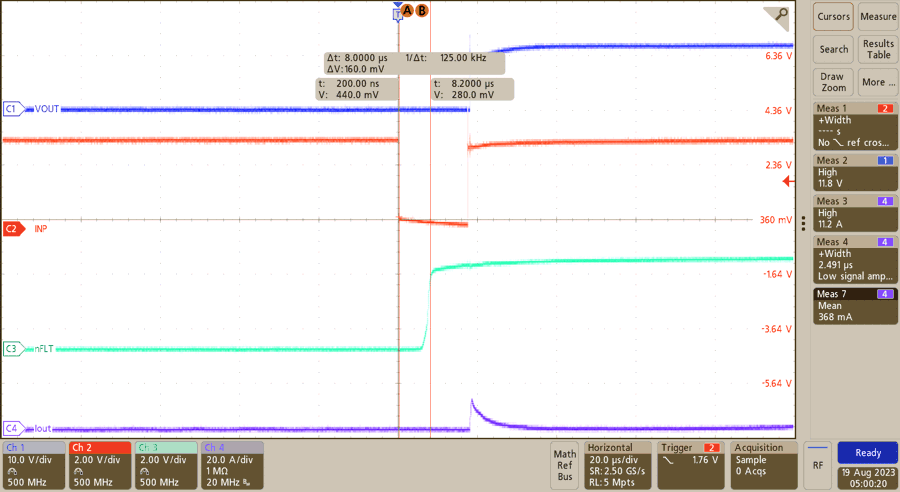
TIDA-020065 Clearing Short-Circuit
                    Latch Figure 4-15 Clearing Short-Circuit Latch