TIDUF45 May   2024


  1.   1
  2.   Description
  3.   Resources
  4.   Features
  5.   Applications
  6.   6
  7. 1System Description
    1. 1.1 Key System Specifications
  8. 2System Overview
    1. 2.1 Block Diagram
    2. 2.2 Design Considerations
    3. 2.3 Highlighted Products
      1. 2.3.1 ADS127L21
      2. 2.3.2 PGA855
      3. 2.3.3 REF70
  9. 3System Design Theory
  10. 4Hardware, Software, Testing Requirements, and Test Results
    1. 4.1 Hardware Description
      1. 4.1.1 Board Interface
      2. 4.1.2 Power Supplies
      3. 4.1.3 Clocking Tree
    2. 4.2 Software Requirements
    3. 4.3 Test Setup
    4. 4.4 Test Results
      1. 4.4.1 DC Accuracy Tests
      2. 4.4.2 Gain and Offset Temperature Drift
      3. 4.4.3 Nonlinearity
      4. 4.4.4 SNR and Noise Performance
  11. 5Design and Documentation Support
    1. 5.1 Design Files
      1. 5.1.1 Schematics
      2. 5.1.2 BOM
    2. 5.2 Software
    3. 5.3 Documentation Support
    4. 5.4 Support Resources
    5. 5.5 Trademarks
  12. 6About the Author

Hardware Description

Figure 4-1 shows the TIDA-010945 hardware, indicating different circuit blocks, connectors, and interfaces from the System Block Diagram.
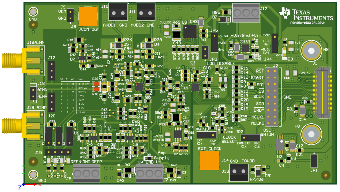
TIDA-010945 Board Layout and
                    Interfaces Figure 4-1 Board Layout and Interfaces