TIDUF45 May 2024
4.4.1 DC Accuracy Tests
Drift and non-linearity are key specifications for DC accuracy, as unlike initial errors like gain and offset errors, these cannot be easily calibrated by using two-point or three-point calibration. In this section, gain and offset drifts and non linearity of the signal chain are measured to calculate the DC accuracy achieved by the signal chain post-calibration.
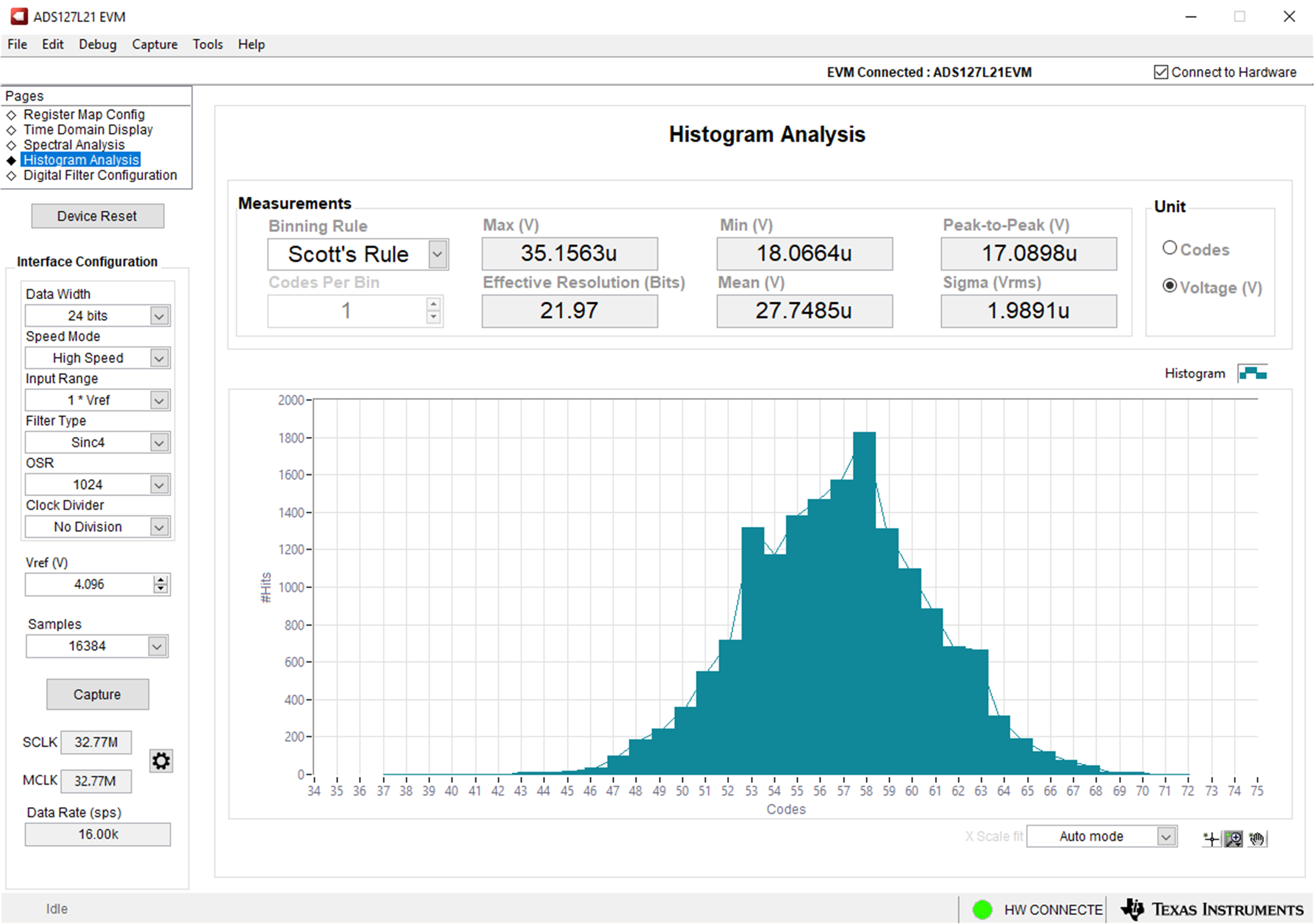
Use jumper J18 to short the inputs together to measure the offset error. Use the GUI to capture data to produce a graph similar to Figure 4-4. Since the output is zero when the inputs are shorted together, any non-zero output is the offset error. Reading the histogram in Figure 4-4, the offset error is 27.7μV.
 Figure 4-4 Offset Measurement (G = 1, TA =
25°C)
Figure 4-4 Offset Measurement (G = 1, TA =
25°C)Remove the short from J18 and collect data from 0V to ± full-scale. The full-scale range (FSR) depends on the reference and the gain settings and can be calculated with the following equation:
Be sure not to violate the input range of the PGA. Repeat the data collection for different gain settings, making sure the temperature chamber settles to the correct temperature before collecting data. Collect data at ± 95% of the full-scale range to perform gain error calculations.
To collect temperature drift data, repeat the same trials over multiple temperatures. To account for reference accuracy error, measure the reference value and input the result into the GUI on the left-hand side, under "Interface Configuration".