TIDUF46 October 2023
3.3.4 Cell Balancing and Thermal Performance
The test uses a battery simulator to test the bottom BQ79616 device of the BMU at room temperature (27°C) and 3.5-V cell voltage. Auto-balancing control is used and CB FETs are enabled in an odd and even manner with a duty cycle of 30 minutes. After 30 minutes of odd or even manner cell balancing, the temperature is stable.
Table 3-10 shows the cell balancing current from a battery simulator. The power supply current to BQ79616 is near 15.3 mA. The cell current of each channel is near 109 mA.
| CELL | CELL VOLTAGE (V) | CURRENT (A) | CELL | CELL VOLTAGE (V) | CURRENT (A) | CELL | CELL VOLTAGE (V) | CURRENT (A) |
|---|---|---|---|---|---|---|---|---|
| 8 | 3.5000 | 0.0153 | 16 | 3.5000 | 0.0150 | 24 | 3.5003 | 0.0000 |
| 7 | 3.5000 | 0.1242 | 15 | 3.5001 | 0.1242 | 23 | 3.5002 | 0.0000 |
| 6 | 3.5003 | 0.0152 | 14 | 3.5001 | 0.0152 | 22 | 3.5001 | 0.0000 |
| 5 | 3.5000 | 0.1241 | 13 | 3.5000 | 0.1242 | 21 | 3.5001 | 0.0000 |
| 4 | 3.4996 | 0.0152 | 12 | 3.5000 | 0.0152 | 20 | 3.5000 | 0.0000 |
| 3 | 3.5005 | 0.1229 | 11 | 3.4998 | 0.1242 | 19 | 3.4998 | 0.0000 |
| 2 | 3.5000 | 0.0152 | 10 | 3.5002 | 0.0152 | 18 | 3.5005 | 0.0000 |
| 1 | 3.4999 | 0.1231 | 9 | 3.5002 | 0.1233 | 17 | 3.5000 | 0.0000 |
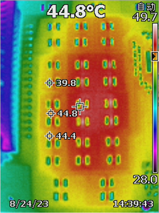
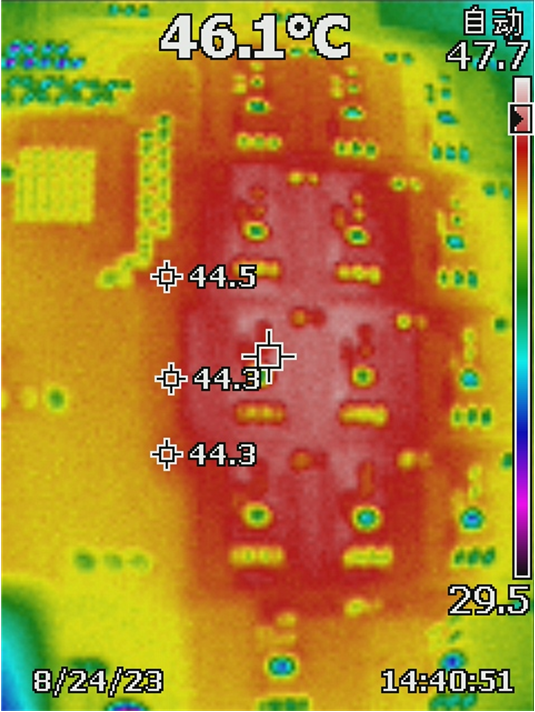
The following images show the cell balancing thermal performance at room temperature. Figure 3-6 is the top side thermal image and Figure 3-7 shows the bottom side thermal image.

Figure 3-6 Top Side of Board

Figure 3-7 Bottom Side of Board
The maximum temperature rise is 19°C.