TIDUF48A November   2023  – February 2024 THS6222 , THS6232


  1.   1
  2.   Description
  3.   Resources
  4.   Features
  5.   Applications
  6.   6
  7. 1System Description
    1. 1.1 Key System Specifications
  8. 2System Overview
    1. 2.1 Block Diagram
    2. 2.2 Highlighted Products
      1. 2.2.1 THVD8000DDF
      2. 2.2.2 THS6222RGTT
      3. 2.2.3 MSPM0G350x
      4. 2.2.4 TPS26624DRCR
      5. 2.2.5 LM5164QDDARQ1
      6. 2.2.6 TPS560430X3FDBVR
      7. 2.2.7 TMUX1204DGSR
    3. 2.3 Design Considerations
      1. 2.3.1 Modulator and Carrier Frequency Selection
      2. 2.3.2 Power Consumption and Gain of the THS6222 Line Driver
      3. 2.3.3 Front End and Discrete Filter
      4. 2.3.4 THVD8000 Schematic
      5. 2.3.5 Board Pinout
  9. 3Hardware, Software, Testing Requirements and Test Results
    1. 3.1 Test Setup
      1. 3.1.1 Powering the TIDA-010935
    2. 3.2 Test Results
  10. 4Design and Documentation Support
    1. 4.1 Design Files
      1. 4.1.1 Schematics
      2. 4.1.2 BOM
    2. 4.2 Documentation Support
    3. 4.3 Support Resources
    4. 4.4 Trademarks
  11. 5About the Author
  12. 6Revision History

Powering the TIDA-010935

Powering the TIDA-010935 requires an input voltage ranging from 13.5 V to 50 V. This is done to match the varying output voltage from a solar panel as it is possible that the output power is not constant. Supplying the TIDA-010935 with solar power is done by connecting the DC cables coming from the solar panel according to the poles described at the J2 and J3 headers. J2 is the positive pole while J3 is the negative pole. To power the board from these connectors, jumper J4 needs to be populated.

Alternatively, the board can be powered by an auxiliary supply connected to the AUX_Supply connector. The same input voltages can be used and the polarity is marked on the board. In this case, do not populate jumper.
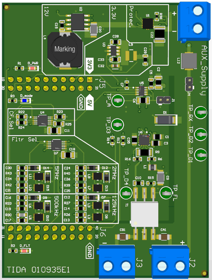
GUID-20231018-SS0I-XPDT-JWVW-ZFDKKKNQKJ9R-low.pngFigure 3-2 Board AUX Supply