TIDUF51 November   2023


  1.   1
  2.   Description
  3.   Resources
  4.   Features
  5.   Applications
  6.   6
  7. 1System Description
    1. 1.1 Key System Specifications
  8. 2System Overview
    1. 2.1 Block Diagram
    2. 2.2 Design Considerations
      1. 2.2.1 mmWave Sensor Application
      2. 2.2.2 IWR6432 UART Communication
      3. 2.2.3 LAUNCHXLCC1352R1 Communication
      4. 2.2.4 Sensors Application
      5. 2.2.5 Power Supply Design
      6. 2.2.6 IWRL6432 Power Supply Considerations
    3. 2.3 Highlighted Products
      1. 2.3.1 IWRL6432
      2. 2.3.2 CC1352R
      3. 2.3.3 BQ25616
      4. 2.3.4 TPS62850
      5. 2.3.5 HDC3020
      6. 2.3.6 OPT3005
      7. 2.3.7 DRV5032
  9. 3Hardware, Software, Testing Requirements, and Test Results
    1. 3.1 Hardware Requirements
      1. 3.1.1 Getting Started Hardware
        1. 3.1.1.1 IWRL6432FSPEVM Initialization: IWRL6432 Programming
        2. 3.1.1.2 Base Board Initialization: CC1352R Programming
    2. 3.2 Software Requirements
    3. 3.3 Test Setup
      1. 3.3.1 Demonstration Setup
    4. 3.4 Test Results
      1. 3.4.1 Radar Detect Distance Measurement
      2. 3.4.2 People Counting Test Results
      3. 3.4.3 Wireless Range Test Results
      4. 3.4.4 Power Consumption Test Results
  10. 4Design and Documentation Support
    1. 4.1 Design Files
      1. 4.1.1 Schematics
      2. 4.1.2 BOM
      3. 4.1.3 PCB Layout Recommendations
        1. 4.1.3.1 Layout Prints
      4. 4.1.4 Altium Project
      5. 4.1.5 Gerber Files
      6. 4.1.6 Assembly Drawings
    2. 4.2 Tools and Software
    3. 4.3 Documentation Support
    4. 4.4 Support Resources
    5. 4.5 Trademarks
  11. 5About the Author

Radar Detect Distance Measurement

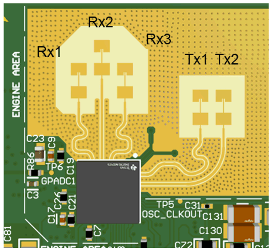
The IWRL6432FSPEVM utilizes the same FR4 based antennas on the PCB as the XWRL6432BOOST. These antennas include three receivers and two transmitters.

GUID-20221129-SS0I-WRPB-ZVRN-ZVLT8PVJ7MQV-low.png

Figure 3-14 TX and RX Antennas of the EVM
Note: The XWRL6432BOOST has an antenna gain of about 5–6 dBi across different antenna pairs.

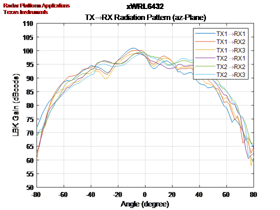
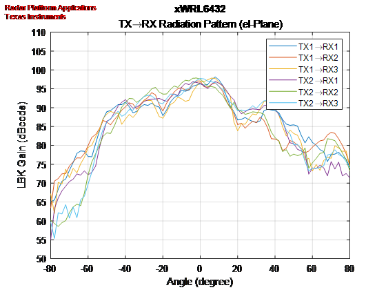
The IWRL6432FSPEVM has same azimuth and elevation antenna radiation patterns as the XWRL6432BOOST.

GUID-4B2CC1EF-64F2-4ADE-B609-B3384CF61799-low.png

Figure 3-15 Azimuth Antenna Radiation Patterns
GUID-486EFFC6-2565-484B-BD3D-9FDDB31DA1B6-low.png

Figure 3-16 Elevation Antenna Radiation Patterns

The results of the radar detect distance measurements are given in Table 3-2.

Table 3-2 Radar Detect Distance
AZIMUTH ANGLE (DEGREE) 0 30 60
Motion localization example(1) 9 m 8 m 5 m
Static localization example(1) 10 m 9 m 6 m
No test beyond 10 m, due to test environment limitation.