TIDUF60 December 2023
- 1
- Description
- Resources
- Features
- Applications
- 6
- 1System Description
-
2System Overview
- 2.1 Block Diagram
- 2.2 Design Considerations
- 2.3 Highlighted Products
- 2.4 System Design Theory
-
3Hardware, Software, Testing Requirements, and Test Results
- 3.1 Getting Started Hardware
- 3.2 Getting Started GUI
- 3.3
Getting Started C2000 Firmware
- 3.3.1 Download and Install Software Required for Board Test
- 3.3.2 Opening Project Inside CCS
- 3.3.3 Project Structure
- 3.3.4 Test Procedure
- 3.4 Test Results
- 3.5 Migrate Firmware to a New Hardware Board
- 3.6 Getting Started MSPM0 Firmware
- 4Design and Documentation Support
- 5About the Author
3.3.4.1.4 Run the Code
To run the code, complete the following steps:
- Run the project by clicking the button
, or click Run → Resume in the Debug tab.
- In the Expressions window, set the variables motorVars_M1.flagEnableRunAndIdentify to "1" after systemVars.flagEnableSystem was automatically set to "1" in the watch window.
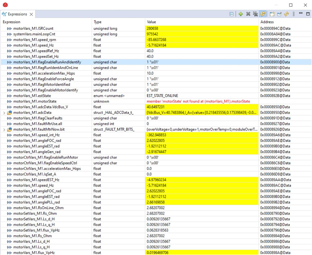
- The project can now run, and the values in the graphs and Expressions window can continuously update as shown in Figure 3-25 while using this project. The windows can be resized according to user preference.
- In the watch view, the variables motorVars_M1.flagRunIdentAndOnLine can be set to "1" automatically. The ISRCount is increasing continuously.
- Check calibration offsets of the motor, the offset value of the motor phase current sensing can be equal to approximately half of the scale current of ADC as shown in Figure 3-25.
- Probe the PWM output for motor drive control with an oscilloscope at J15 as shown in Figure 3-23. All of the PWM duty are set to 50% in this build level, the PWM output waveforms are as shown in Figure 3-26. The PWM switching frequency of motor_1 is 15 kHz.
- The controller can now be halted, and the debug connection terminated. Fully halt the controller by first clicking the Halt button
on the toolbar or by clicking Target → Halt. Finally, reset the controller by clicking on
or clicking Run → Reset.
- Erase the code in the controller for the next build level by clicking Tools → On-Chip Flash, and click Erase Flash in the On-Chip Flash tab (make sure that all of the flash banks are checked) as shown in Figure 3-27. This operation erases all of the program code stored in flash. (This step is optional, the user can ignore this step to load the new program code in next build level.)Note: Do not click Cancel, turn off the power of the board, or disconnect the emulator when erasing flash.
- Close the CCS debug session by clicking the Terminate Debug Session button
or clicking Run → Terminate.
 Figure 3-25 Build Level 1: Expressions Window at Run Time
 Figure 3-26 Build Level 1: MCU PWM Output and IPM Output
 Figure 3-27 Build Level 1: Erase Program Code in Flash for Next Build Level