TIDUF60 December 2023
- 1
- Description
- Resources
- Features
- Applications
- 6
- 1System Description
-
2System Overview
- 2.1 Block Diagram
- 2.2 Design Considerations
- 2.3 Highlighted Products
- 2.4 System Design Theory
-
3Hardware, Software, Testing Requirements, and Test Results
- 3.1 Getting Started Hardware
- 3.2 Getting Started GUI
- 3.3
Getting Started C2000 Firmware
- 3.3.1 Download and Install Software Required for Board Test
- 3.3.2 Opening Project Inside CCS
- 3.3.3 Project Structure
- 3.3.4 Test Procedure
- 3.4 Test Results
- 3.5 Migrate Firmware to a New Hardware Board
- 3.6 Getting Started MSPM0 Firmware
- 4Design and Documentation Support
- 5About the Author
3.3.4.3.4 Run the Code
To run the code, complete the following steps:
- Set the AC source output to 0 V at 50/60 Hz, turn on the AC power supply, slowly increase the input voltage from 0-V to 220-V AC.
- Run the project by clicking the
button, or click Run → Resume in the Debug tab. Set systemVars.flagEnableSystem to "1" after a fixed time, that means the offsets calibration has been done and the power relay for inrush is turned on. The motor fault flags for motorVars_M1.faultMtrUse.all need to equal to "0" , if the values do not, check the current and voltage sensing circuit as described in Section 3.3.4.1.
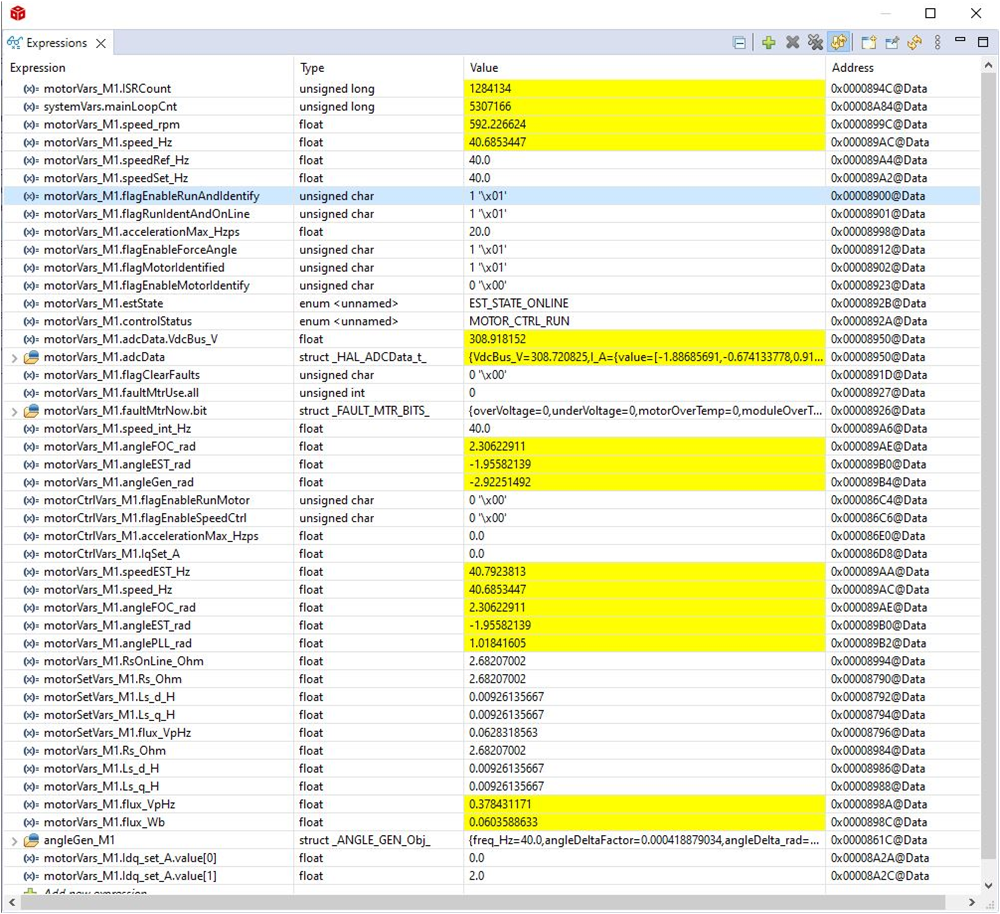
- To verify current closed-loop control for motor, set the variable motorVars_M1.flagEnableRunAndIdentify to "1" in the Expressions window as shown in Figure 3-33. The motor needs to run with a closed-loop control using the angle from the angle generator at a setting speed in the variable motorVars_M1.speedRef_Hz, check the value of motorVarsM1.speed_Hz in Expressions window, both variables value need to be very close.
- The motor current Iq can be set and changed with motorVars_M1.Idq_Set_A.value[1]
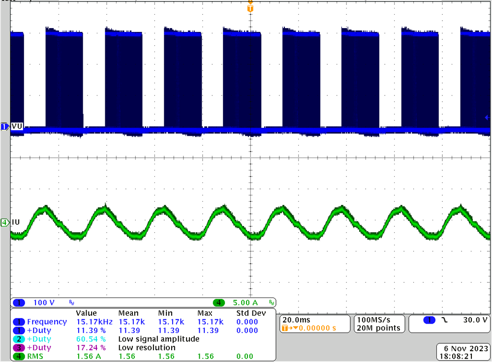
- Connect oscilloscope probes to IPM output to watch the motor phase voltage and current as shown in Figure 3-34. Change the Idq_set_A[0].value[1] in the Expressions window, the motor phase current needs to be increasing accordingly.
- If the motor cannot run with current-closed loop and appears to experience an overcurrent fault, check if the sign of adcData[0].current_sf and the value of userParams[0].current_sf are set correctly according to the hardware board.
- The controller can now be halted before setting
the motorVars_M1.flagEnableRunAndIdentify to "0", and the debug
connection terminated. Fully halting the controller by first clicking the
Halt button
on the toolbar or by clicking Target → Halt. Finally, reset the controller by clicking on
or clicking Run → Reset.
- Close CCS debug session by clicking on
Terminate Debug Session
or clicking Run → Terminate.
 Figure 3-33 Build Level 3: Expressions Window at Run Time
 Figure 3-34 Build Level 3: Motor Current Under 2-A
IQ Setting