TIDUF60 December 2023
- 1
- Description
- Resources
- Features
- Applications
- 6
- 1System Description
-
2System Overview
- 2.1 Block Diagram
- 2.2 Design Considerations
- 2.3 Highlighted Products
- 2.4 System Design Theory
-
3Hardware, Software, Testing Requirements, and Test Results
- 3.1 Getting Started Hardware
- 3.2 Getting Started GUI
- 3.3
Getting Started C2000 Firmware
- 3.3.1 Download and Install Software Required for Board Test
- 3.3.2 Opening Project Inside CCS
- 3.3.3 Project Structure
- 3.3.4 Test Procedure
- 3.4 Test Results
- 3.5 Migrate Firmware to a New Hardware Board
- 3.6 Getting Started MSPM0 Firmware
- 4Design and Documentation Support
- 5About the Author
3.2.1 Test Setup
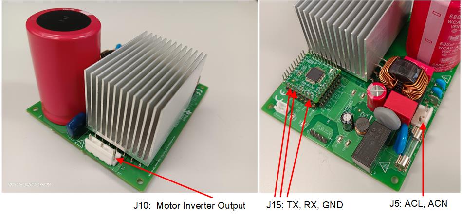
The GUI software needs only a UART connection between the host PC and the reference design board. Figure 3-3 shows the hardware connection for testing with the GUI. Setup the hardware using the following steps:
- Connect only TX, RX, and GND on J15 to the host PC through a UART-to-USB adapter. 3.3 V is not needed from the adapter.
- Connect motor wires to J10.
- Connect the multimeter, oscilloscope probes, and other measurement equipment to probe or analyze various signals and parameters
- Power on the board with a DC bus power, AC power
supply or AC mains power to the inverter at J5 and J7.
- The maximum output of the DC power supply is 380 VDC.
- The maximum output of the AC power supply is 265 VAC, 50/60 Hz.
- AC main power is 220 VAC, 50/60 Hz.
 Figure 3-3 Hardware Connection for Testing With GUI
Software
Figure 3-3 Hardware Connection for Testing With GUI
SoftwareNote: Add ferrite beads on JTAG signals and the USB
cable if the external emulator has connectivity issues while testing. Make the
connection lines as short as possible.
WARNING: The ground planes of both the
power domains can be the same or different depending on the hardware configuration.
Meet proper isolation requirements before connecting any test equipment with the
board for personal safety and to prevent damaging equipment. Review the GND
connections before powering the board. An isolator is required if measurement
equipment is connected to the board.