TIDUF65 March 2024
- 1
- Description
- Resources
- Features
- Applications
- 6
- 1System Description
- 2System Overview
- 3System Design Theory
- 4Hardware, Software, Testing Requirements, and Test Results
- 5Performance Comparison with Competitor’s Device
- 6Design and Documentation Support
- 7About the Author
4.4.3 PWM Rejection
During PWM switching, the phase current suffers large common-mode voltage transients of up to 10kV/μs with an IGBT based 3-phase inverter, which can affect the accuracy of current sensor. Therefore the PWM rejection, also called common-mode transient immunity (CMTI) is an important parameter to provide accurate current measurement. To test the PWM rejection of the TMCS1123, a 3-phase inverter with 320VDC bus (TIDA-010025) and an AC motor were used. The TMCS1123 on the TIDA-010937 was connected to the phase U of the 3-phase inverter and the software on the C200 MCU was configured to sample the phase current with the ADS7043 data converter over 1200 PWM periods, while continuously changing the start of conversion time of the ADC from the beginning of the PWM cycle to the end of the PWM cycle increasing the system-on-chip (SoC) in 60ns steps every new PWM cycle. This results in an equivalent 16MHz sampled current measurement over one PWM period. To make sure the current does not change over the 1200 PWM periods (10kHz PWM period), the current was impressed to 3A DC. The test setup is shown in Figure 4-13.
 Figure 4-13 TMCS1123 PWM Rejection Test
Setup
Figure 4-13 TMCS1123 PWM Rejection Test
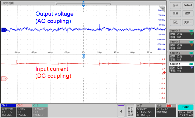
SetupIn Figure 4-14, the blue curve is the oscilloscope waveform of the output voltage and the red curve is the input current of the TMCS1123 measured with a current probe. The TIDA-010025 outputs a 3A average DC current. The small transient noise spikes are due to the oscilloscope being sensitive to the IGBT inverter PWM switching.
 Figure 4-14 Oscilloscope Measurement of
Output Voltage and Input Current of TMCS1123
Figure 4-14 Oscilloscope Measurement of
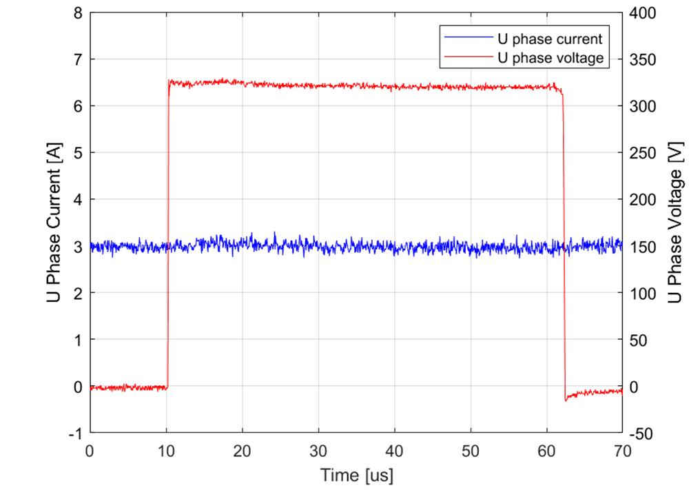
Output Voltage and Input Current of TMCS1123Figure 4-15 shows the phase-current measurement (blue using the ADS7043 SAR ADC as explained earlier). The blue curve is the waveform of the U phase current measured with the time triggered ADS7043, as described earlier (16MHz equivalent sample rate) and the red curve is U phase voltage waveform. There is no ringing during PWM switching on the TMCS1123 output; therefore, the TMCS1123 also retains high accuracy during the PWM switching.
 Figure 4-15 TMCS1123 Current Over One PWM
Cycle Samples With Time Triggered ADS7043 ADC