TIDUF67 April   2024


  1.   1
  2.   Description
  3.   Resources
  4.   Features
  5.   Applications
  6.   6
  7. 1System Description
    1. 1.1 Terminology
    2. 1.2 Key System Specifications
  8. 2System Overview
    1. 2.1 Block Diagram
    2. 2.2 Highlighted Products
      1. 2.2.1 AM263x Microcontrollers
        1. 2.2.1.1 TMDSCNCD263
        2. 2.2.1.2 LP-AM263
  9. 3System Design Theory
    1. 3.1 Three-Phase PMSM Drive
      1. 3.1.1 Mathematical Model and FOC Structure of PMSM
      2. 3.1.2 Field Oriented Control of PM Synchronous Motor
        1. 3.1.2.1 The ( a ,   b ) ⇒ ( α , β ) Clarke Transformation
        2. 3.1.2.2 The α , β ⇒ ( d ,   q ) Park Transformation
        3. 3.1.2.3 The Basic Scheme of FOC for AC Motor
        4. 3.1.2.4 Rotor Flux Position
      3. 3.1.3 Sensorless Control of PM Synchronous Motor
        1. 3.1.3.1 Enhanced Sliding Mode Observer With Phase Locked Loop
          1. 3.1.3.1.1 Design of ESMO for PMSM
          2. 3.1.3.1.2 Rotor Position and Speed Estimation with PLL
      4. 3.1.4 Hardware Prerequisites for Motor Drive
      5. 3.1.5 Additional Control Features
        1. 3.1.5.1 Field Weakening (FW) and Maximum Torque Per Ampere (MTPA) Control
        2. 3.1.5.2 Flying Start
  10. 4Hardware, Software, Testing Requirements, and Test Results
    1. 4.1 Hardware Requirements
    2. 4.2 Software Requirements
      1. 4.2.1 Importing and Configuring Project
      2. 4.2.2 Project Structure
      3. 4.2.3 Lab Software Overview
    3. 4.3 Test Setup
      1. 4.3.1 LP-AM263 Setup
      2. 4.3.2 BOOSTXL-3PHGANINV Setup
      3. 4.3.3 TMDSCNCD263 Setup
      4. 4.3.4 TMDSADAP180TO100 Setup
      5. 4.3.5 TMDSHVMTRINSPIN Setup
    4. 4.4 Test Results
      1. 4.4.1 Level 1 Incremental Build
        1. 4.4.1.1 Build and Load Project
        2. 4.4.1.2 Setup Debug Environment Windows
        3. 4.4.1.3 Run the Code
      2. 4.4.2 Level 2 Incremental Build
        1. 4.4.2.1 Build and Load Project
        2. 4.4.2.2 Setup Debug Environment Windows
        3. 4.4.2.3 Run the Code
      3. 4.4.3 Level 3 Incremental Build
        1. 4.4.3.1 Build and Load Project
        2. 4.4.3.2 Setup Debug Environment Windows
        3. 4.4.3.3 Run the Code
      4. 4.4.4 Level 4 Incremental Build
        1. 4.4.4.1 Build and Load Project
        2. 4.4.4.2 Setup Debug Environment Windows
        3. 4.4.4.3 Run the Code
    5. 4.5 Adding Additional Functionality to Motor Control Project
      1. 4.5.1 Using DATALOG Function
      2. 4.5.2 Using PWMDAC Function
      3. 4.5.3 Adding CAN Functionality
      4. 4.5.4 Adding SFRA Functionality
        1. 4.5.4.1 Principle of Operation
        2. 4.5.4.2 Object Definition
        3. 4.5.4.3 Module Interface Definition
        4. 4.5.4.4 Using SFRA
    6. 4.6 Building a Custom Board
      1. 4.6.1 Building a New Custom Board
        1. 4.6.1.1 Hardware Setup
        2. 4.6.1.2 Migrating Reference Code to a Custom Board
          1. 4.6.1.2.1 Setting Hardware Board Parameters
          2. 4.6.1.2.2 Modifying Motor Control Parameters
          3. 4.6.1.2.3 Changing Pin Assignment
          4. 4.6.1.2.4 Configuring the PWM Module
          5. 4.6.1.2.5 Configuring the ADC Module
          6. 4.6.1.2.6 Configuring the CMPSS Module
  11. 5General Texas Instruments High Voltage Evaluation (TI HV EVM) User Safety Guidelines
  12. 6Design and Documentation Support
    1. 6.1 Design Files
      1. 6.1.1 Schematics
      2. 6.1.2 BOM
      3. 6.1.3 PCB Layout Recommendations
        1. 6.1.3.1 Layout Prints
    2. 6.2 Tools and Software
    3. 6.3 Documentation Support
    4. 6.4 Support Resources
    5. 6.5 Trademarks
  13. 7About the Author

LP-AM263 Setup

LP-AM263 is a low-cost development board for the TI Arm®-based real-time microcontrollers. This LaunchPad kit offers extra pins for development and supports the connection of two BoosterPack™ plug-in modules.

  • For more details about the LP-AM263 , see the LP-AM263 LaunchPad User's Guide.
  • Make sure that the boot switch on the LP-AM263 are set as shown in Figure 4-6.
    • For QSPI_D0 (SOP0), position the switch to the LEFT (Logic High).
    • For QSPI_D1 (SOP1), position the switch to the LEFT (Logic High).
    • For SPI0_CLK_pad (SOP2), position the switch to the Right (Logic Low).
    • For SPI0_D0_pad (SOP3), position the switch to the LEFT (Logic High).
  • Make sure that the DAC VREF Switch (S1) on the LP-AM263 is set on AM263x on-die LDO for correct CMPSS Operation.
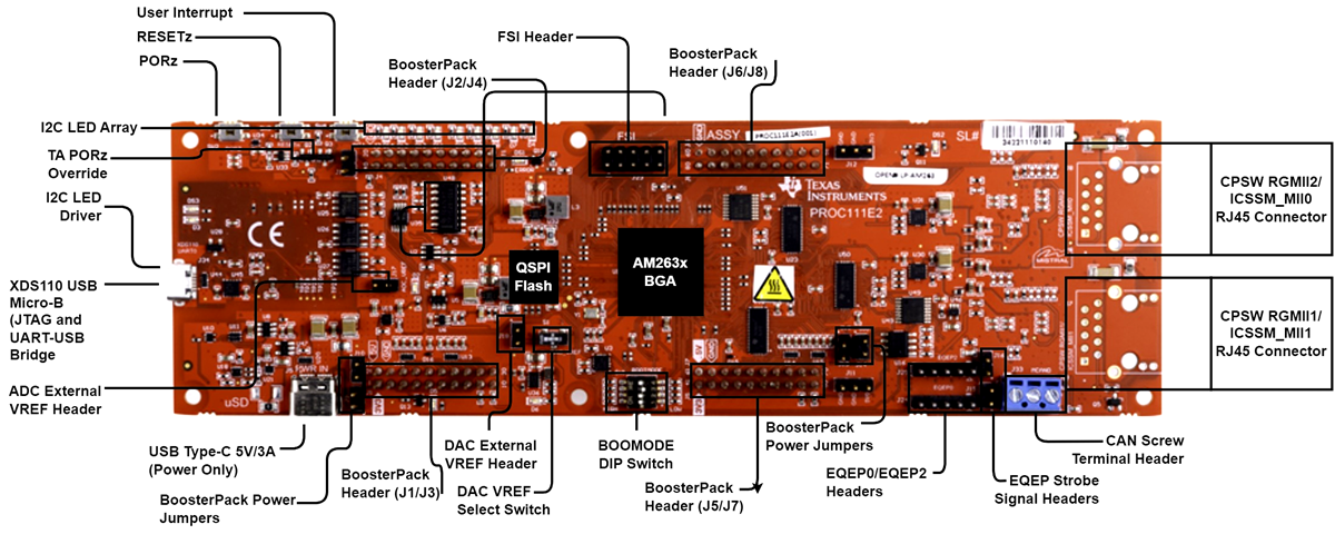
GUID-20240320-SS0I-TJ6Z-PSTD-L0NW7RRQ0LQ8-low.png Figure 4-6 LP-AM263 LaunchPad™ Board Overview and Switches Setting