TIDUF68 February   2024


  1.   1
  2.   Description
  3.   Resources
  4.   Features
  5.   Applications
  6.   6
  7. 1System Description
    1. 1.1 Key System Specifications
  8. 2System Overview
    1. 2.1 Block Diagram
    2. 2.2 Design Considerations
    3. 2.3 Highlighted Products
      1. 2.3.1 LMG2100
      2. 2.3.2 INA241A
      3. 2.3.3 LMR38010
  9. 3System Design Theory
    1. 3.1 Three-Phase GaN Inverter Power Stage
      1. 3.1.1 LMG2100 GaN Half-Bridge Power Stage
    2. 3.2 Inline Shunt Precision-Phase Current Sensing With INA241A
    3. 3.3 Phase Voltage and DC Input Voltage Sensing
    4. 3.4 Power-Stage PCB Temperature Monitor
    5. 3.5 Power Management
      1. 3.5.1 48V to 5V DC/DC Converter
      2. 3.5.2 5V to 3.3V Rail
    6. 3.6 Interface to Host MCU
  10. 4Hardware, Software, Testing Requirements, and Test Results
    1. 4.1 Hardware Requirements
      1. 4.1.1 TIDA-010936 PCB Overview
      2. 4.1.2 TIDA-010936 Jumper Settings
      3. 4.1.3 Interface to C2000™ MCU LaunchPad™ Development Kit
    2. 4.2 Software Requirements
    3. 4.3 Test Setup
    4. 4.4 Test Results
      1. 4.4.1 Power Management and System Power Up and Power Down
    5. 4.5 GaN Inverter Half-Bridge Module Switch Node Voltage
      1. 4.5.1 Switch Node Voltage Transient Response at 48V DC Bus
        1. 4.5.1.1 Output Current at ±1A
        2. 4.5.1.2 Output Current at ±10A
      2. 4.5.2 Impact of PWM Frequency to DC-Bus Voltage Ripple
      3. 4.5.3 Efficiency Measurements
      4. 4.5.4 Thermal Analysis
      5. 4.5.5 No Load Loss Test (COSS Losses)
  11. 5Design and Documentation Support
    1. 5.1 Design Files {Required Topic}
      1. 5.1.1 Schematics
      2. 5.1.2 BOM
      3. 5.1.3 PCB Layout Recommendations
        1. 5.1.3.1 Layout Prints
      4. 5.1.4 Altium Project
      5. 5.1.5 Gerber Files
      6. 5.1.6 Assembly Drawings
    2. 5.2 Tools and Software
    3. 5.3 Documentation Support
    4. 5.4 Support Resources
    5. 5.5 Trademarks
  12. 6About the Author
  13. 7Recognition

Power Management and System Power Up and Power Down

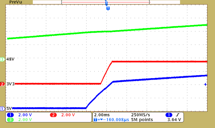
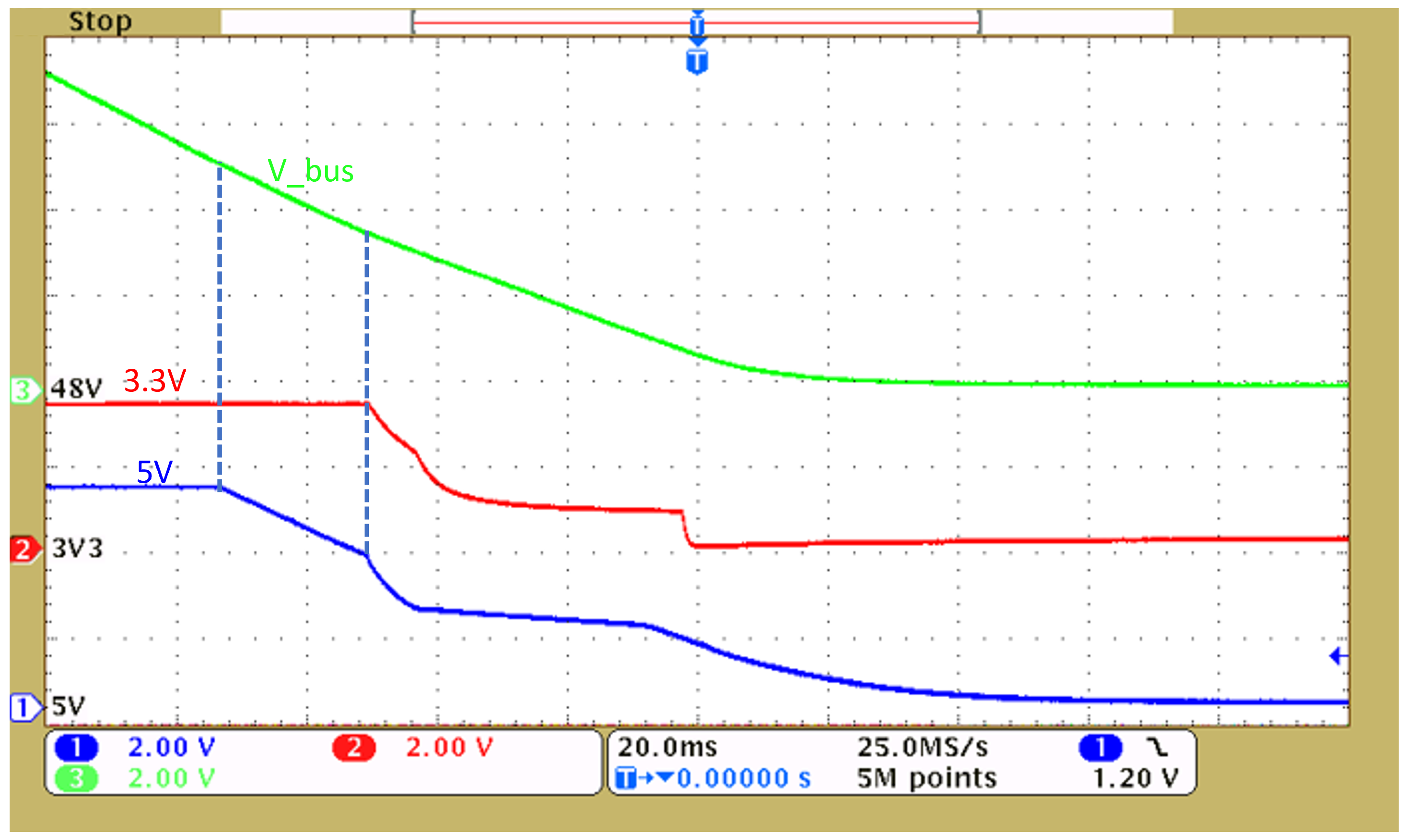
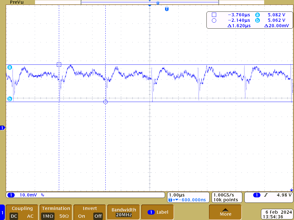
The focus of this test was to validate the onboard 5V and 3.3V power supplies and measure the typical current consumption of the 3.3V and 5V rail. For these tests, the C2000 MCU LaunchPad development kit was not powered from the TIDA-010936. Due to the high step-down ratio 48:5 (48V input to 5V output), the voltage ripple at the 5V rail was validated too.

GUID-20240220-SS0I-Z72F-39WX-HCBJZJK08QHX-low.png

Figure 4-4 TIDA-010936 System Power Up (48VIN, 5V Rail, and 3.3V Rail)
GUID-20240220-SS0I-KGN3-XBDC-1CDR72CKDSGJ-low.png

Figure 4-5 TIDA-010936 System Power Down (48VIN, 5V Rail, and 3.3V Rail)

For the power-down stage, when the bus voltage drops to about 5V, the output of the LMR38010 drops along with the bus voltage. When the bus is lower than 3.3V, the 3.3V rail also starts to drop.

The AC ripple of the 5V rail remains well below 20mVPP in light load. The frequency of ripple is 617kHz, which matches the buck converter switching frequency. The offset of the 5V rail is about 5.07V.

GUID-20240220-SS0I-R9PN-HLWV-M0FNFH3GJDZX-low.png

Figure 4-6 5V Output Ripple at Nominal Load (20mA)