TIDUF72 August 2024
- 1
- Description
- Resources
- Features
- Applications
- 6
- 1System Description
- 2System Overview
-
3Hardware, Software, Testing Requirements, and Test Results
- 3.1
Hardware Requirements
- 3.1.1 Software Requirements
- 3.1.2 UART for PC GUI Communication
- 3.1.3 Direct Memory Access (DMA)
- 3.1.4 ADC Setup
- 3.1.5 Foreground Process
- 3.1.6 Formulas
- 3.1.7 Background Process
- 3.1.8 Software Function per_sample_dsp()
- 3.1.9 Voltage and Current Signals
- 3.1.10 Pure Waveform Samples
- 3.1.11 Frequency Measurement and Cycle Tracking
- 3.1.12 LED Pulse Generation
- 3.1.13 Phase Compensation
- 3.2
Test Setup
- 3.2.1 Power Supply Options and Jumper Setting
- 3.2.2 Electricity Meter Metrology Accuracy Testing
- 3.2.3 Viewing Metrology Readings and Calibration
- 3.2.4 Calibration and FLASH Settings for MSPM0+ MCU
- 3.2.5 Gain Calibration
- 3.2.6 Voltage and Current Gain Calibration
- 3.2.7 Active Power Gain Calibration
- 3.2.8 Offset Calibration
- 3.2.9 Phase Calibration
- 3.3 Test Results
- 3.1
Hardware Requirements
- 4Design and Documentation Support
- 5About the Authors
3.2.6 Voltage and Current Gain Calibration
To calibrate the voltage and current readings, perform the following steps:
- Connect the GUI to view results for voltage, current, active power, and the other metering parameters.
- Configure the test source to supply the desired voltage and current for all phases. Make sure that these are the voltage and current calibration points with a zero-degree phase shift between each phase voltage and current. For example, for 120V, 10A, 0° (PF = 1). Typically, these values are the same for every phase.
- Click on the Manual cal.
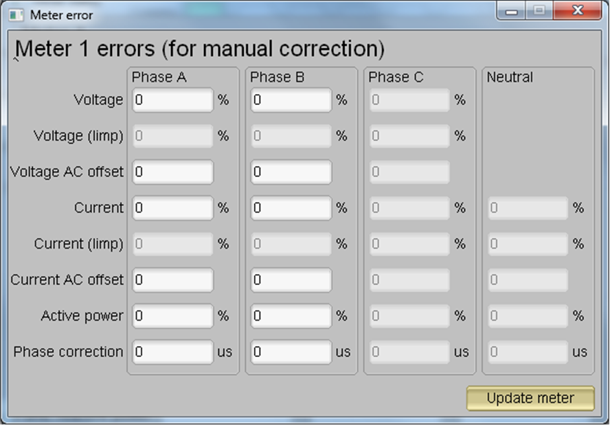
button in Figure 3-12. The screen in Figure 3-14 pops up:
 Figure 3-14 Manual Calibration Window
 - Calculate the correction values for
each voltage and current. The correction values that must be entered for the
voltage and current fields are calculated using Equation 25: Equation 25.

where
- valueobserved is the value measured by the TI meter
- valuedesired is the calibration point configured in the AC test source
- After calculating for all voltages
and currents, input these values as is (±) for the fields
Voltage and Current for the corresponding phases. - Click on the Update meter button and the observed values for the voltages and currents on the GUI settle immediately to the desired voltages and currents.