TIDUF76 June 2024
2.4.9 Dynamic Clutter Removal
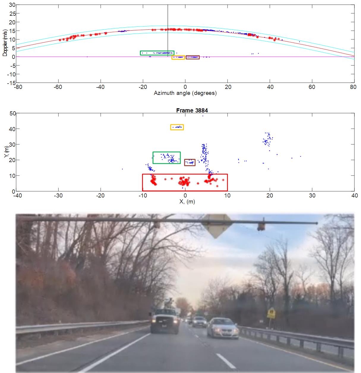
Dynamic clutter removal is an optional feature in the BSD demo processing chain designed to eliminate reflections from stationary roadside objects and the road, referred to as "dynamic clutter." A common feature of dynamic clutter is that all stationary points in the radial velocity-azimuth angle coordinate system are positioned alongside a sinusoidal curve, referred to as the "velocity profile." The velocity profile, shown in Figure 2-8, can be represented as
where Vs denotes the speed of the sensor and α denotes the sensor mounting angle.

Figure 2-8 Velocity Profile of Dynamic Clutter
By estimating Vs and α from near-range detected points, the dynamic clutter removal algorithm is able to filter dynamic clutter from other points that are relevant for the BSD application.
In the BSD demo, clutter removal is performed by the Dynamic Clutter Removal DPU located between AoA2D DPU and the Group Tracker DPU as shown in Figure 2-4. The stationary points are removed from the point cloud list after the AoA2D DPU, and the remaining points, the major points, are supplied to the tracker DPU. The clutter points can optionally be saved and appended to the point cloud list, and at the end of the processing can sent out together with the major points to the GUI visualizer.

Figure 2-9 Dynamic Clutter Removal Implementation
The clutter removal implemented in the BSD demo is depicted in Figure 2-8. The bottom of the figure shows the scene facing the sensor mounted at the rear of the moving vehicle. The middle section illustrates the point clouds corresponding to the scene in the x-y plane, while the top section illustrates the same point-cloud in the radial velocity-azimuth angle plane. Points within the red rectangle in the near range highlighted in red are assumed to mainly represent reflections from the road surface. Points within the yellow, green and purple rectangles correspond to reflections from the three vehicles. The remaining points represent reflections from other stationary objects. In the velocity-azimuth plane, points attributed to stationary objects clearly align within a narrow corridor following the velocity profile curve. With knowledge of Vs and α, these points can be easily filtered out.