TIDUF77 June 2024 – December 2024 MSPM0G1507
- 1
- Description
- Resources
- Features
- Applications
- 6
- 1System Description
-
2System Overview
- 2.1 Block Diagram
- 2.2 Design Considerations
- 2.3 Highlighted Products
- 2.4
System Design Theory
- 2.4.1
Hardware Design
- 2.4.1.1 Modular Design
- 2.4.1.2 Auxiliary Flyback Power Supply
- 2.4.1.3 DC Link Voltage Sensing
- 2.4.1.4 Inrush Current Protection
- 2.4.1.5 Motor Phase Voltage Sensing
- 2.4.1.6 Motor Phase Current Sensing
- 2.4.1.7 Over Current Protection of DRV7308
- 2.4.1.8 Internal Overcurrent Protection for TMS320F2800F137
- 2.4.2 Three-Phase PMSM Drive
- 2.4.1
Hardware Design
-
3Hardware, Software, Testing Requirements, and Test Results
- 3.1 Getting Started Hardware
- 3.2 Getting Started GUI
- 3.3
Getting Started C2000 Firmware
- 3.3.1 Download and Install Software Required for Board Test
- 3.3.2 Opening Project Inside CCS
- 3.3.3 Project Structure
- 3.3.4 Test Procedure
- 3.4
Test Results
- 3.4.1 Fast and clean Rising/Falling Edge
- 3.4.2 Inrush Current Protection
- 3.4.3 Thermal performance under 300VDC
- 3.4.4 Thermal performance under 220VAC
- 3.4.5 Overcurrent Protection by Internal CMPSS
- 3.4.6 IPM Efficiency with External Bias Supply under 300VDC
- 3.4.7 Board Efficiency with Onboard Bias Supply under 300VDC
- 3.4.8 Board Efficiency with External Bias Supply under 220VAC
- 3.4.9 Board Efficiency with Onboard Bias Supply under 220VAC
- 3.4.10 iTHD Test of Motor Phase Current
- 3.4.11 Standby Power Test
- 3.5 Migrate Firmware to a New Hardware Board
- 3.6 Getting Started MSPM0 Firmware
- 4Design and Documentation Support
- 5About the Author
3.3.3 Project Structure
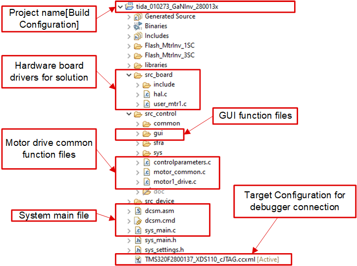
Once the project is imported, the project explore appears inside CCS as shown in Figure 3-20. The device peripherals configuration is based on C2000Ware driverlib. The users only needs to change the codes and definitions in hal.c and hal.h.
The folder src_control includes hal.c and user_mtr1.c, in which users can change codes and definitions.
The folder src_board includes board drivers for this hardware board.
The folder src_control includes motor drive files that call motor control core algorithm functions within the interrupt service routines and background tasks.
 Figure 3-20 TIDA-010273 Project Explorer View
Figure 3-21 shows the project software flow diagram of ISR for motor control, a main loop for motor control parameters update in background loop.
 Figure 3-21 Firmware Project Flow Diagram
The project consists of a motor control interrupt service routine, which are called every PWM cycle. A few background tasks are called in a loop forever in main() and can be used to run slow tasks for which absolute timing accuracy is not required, motor control parameters update, and so on. A CPU timer is used to trigger slow background tasks.
motor1CtrlISR is reserved for calling the motor drive control algorithms to spin the motor that is periodically triggered at USER_M1_ISR_FREQ_Hz.
To simplify the system, the bring up and design of the software for this reference design is organized in four labs with incremental builds (DMC_BUILDLEVEL), which makes learning and getting familiar with the board and software easier. This approach is also good for debugging and testing boards. Table 3-1 lists the detailed incremental build options. To select a particular build option, select the corresponding BUILDLEVEL option in sys_settings.h. Once the build option is selected, compile the project by selecting the rebuild all compiler option. Section 3.3.4 provides more details to run each of the build level options.
| OPERATION | BUILD OPTION | DESCRIPTION |
|---|---|---|
| MOTOR DRIVE | DMC_LEVEL_1 | 50% PWM duty, verify ADC offset calibration, PWM output and phase shift |
| DMC_LEVEL_2 | Open-loop v/f control to check current and voltage sensing signals for motor | |
| DMC_LEVEL_3 | Closed current loop to check the hardware settings | |
| DMC_LEVEL_4 | Motor parameters identify and run with InstaSPIN-FOC or eSMO |