TIDUF77 June 2024 – December 2024 MSPM0G1507
- 1
- Description
- Resources
- Features
- Applications
- 6
- 1System Description
-
2System Overview
- 2.1 Block Diagram
- 2.2 Design Considerations
- 2.3 Highlighted Products
- 2.4
System Design Theory
- 2.4.1
Hardware Design
- 2.4.1.1 Modular Design
- 2.4.1.2 Auxiliary Flyback Power Supply
- 2.4.1.3 DC Link Voltage Sensing
- 2.4.1.4 Inrush Current Protection
- 2.4.1.5 Motor Phase Voltage Sensing
- 2.4.1.6 Motor Phase Current Sensing
- 2.4.1.7 Over Current Protection of DRV7308
- 2.4.1.8 Internal Overcurrent Protection for TMS320F2800F137
- 2.4.2 Three-Phase PMSM Drive
- 2.4.1
Hardware Design
-
3Hardware, Software, Testing Requirements, and Test Results
- 3.1 Getting Started Hardware
- 3.2 Getting Started GUI
- 3.3
Getting Started C2000 Firmware
- 3.3.1 Download and Install Software Required for Board Test
- 3.3.2 Opening Project Inside CCS
- 3.3.3 Project Structure
- 3.3.4 Test Procedure
- 3.4
Test Results
- 3.4.1 Fast and clean Rising/Falling Edge
- 3.4.2 Inrush Current Protection
- 3.4.3 Thermal performance under 300VDC
- 3.4.4 Thermal performance under 220VAC
- 3.4.5 Overcurrent Protection by Internal CMPSS
- 3.4.6 IPM Efficiency with External Bias Supply under 300VDC
- 3.4.7 Board Efficiency with Onboard Bias Supply under 300VDC
- 3.4.8 Board Efficiency with External Bias Supply under 220VAC
- 3.4.9 Board Efficiency with Onboard Bias Supply under 220VAC
- 3.4.10 iTHD Test of Motor Phase Current
- 3.4.11 Standby Power Test
- 3.5 Migrate Firmware to a New Hardware Board
- 3.6 Getting Started MSPM0 Firmware
- 4Design and Documentation Support
- 5About the Author
3.2.4 Motor Identification
Implementing the correct motor parameters is critical for the firmware to control the motor successfully. The parameters include Stator resistance, Stator inductance, flux, and so forth, and those parameters have a default value for a default motor inside the firmware.
For a different PMSM motor, those parameters are usually found from the specification; however, if those parameters cannot be found, the GUI software can identify those parameters.
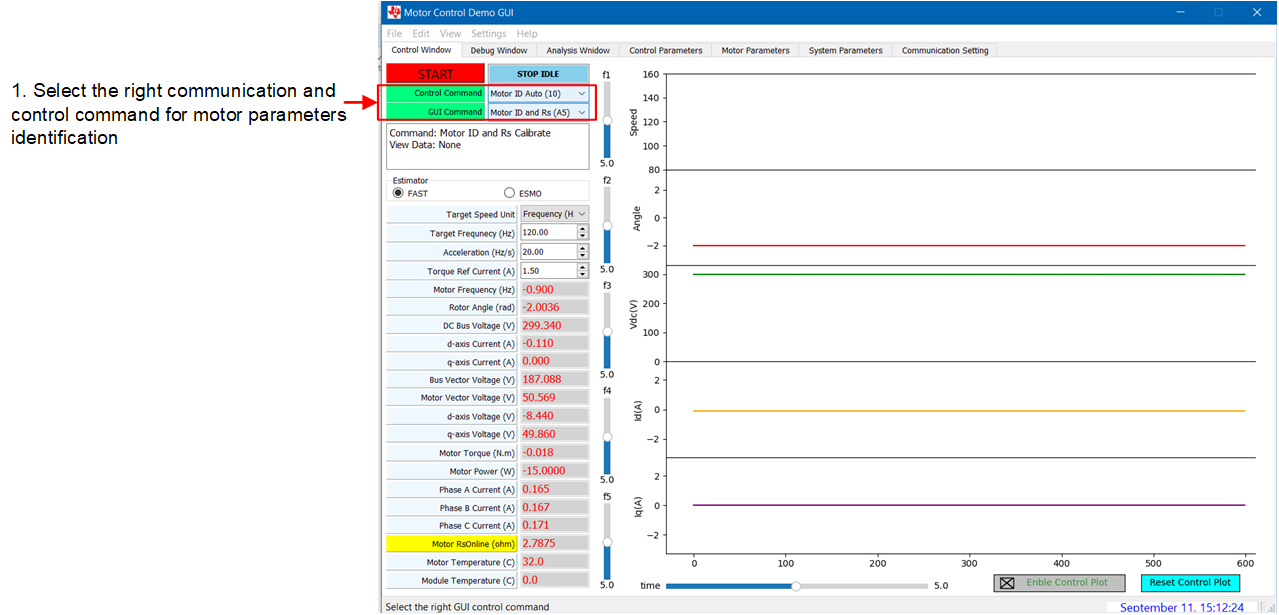
First, choose the motor identification command in the Control Window tab as shown in Figure 3-7.
 Figure 3-7 Motor Identification
Command
Figure 3-7 Motor Identification
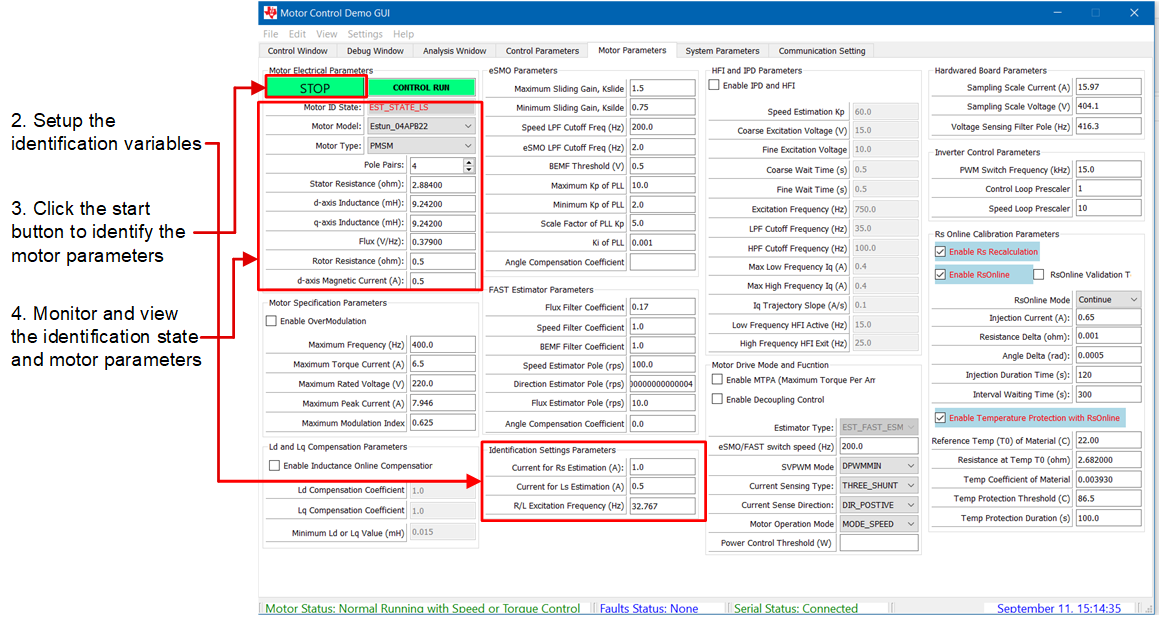
CommandNext, select the Motor Parameters tab. The motor identification applies current to the motor to estimate motor parameters, those identification parameters, such as current for stator resistor estimation, current for stator inductor estimation and R/L Excitation Frequency (Hz) can be changed or left on the default settings.
Click the START button to start motor identification. An audible noise is heard, and the motor spins at low speed during identification. Monitor the identification status and motor parameters, the overall identification time is about 2 minutes. Figure 3-8 shows the steps to start motor identification.
 Figure 3-8 Start Motor
Identification
Figure 3-8 Start Motor
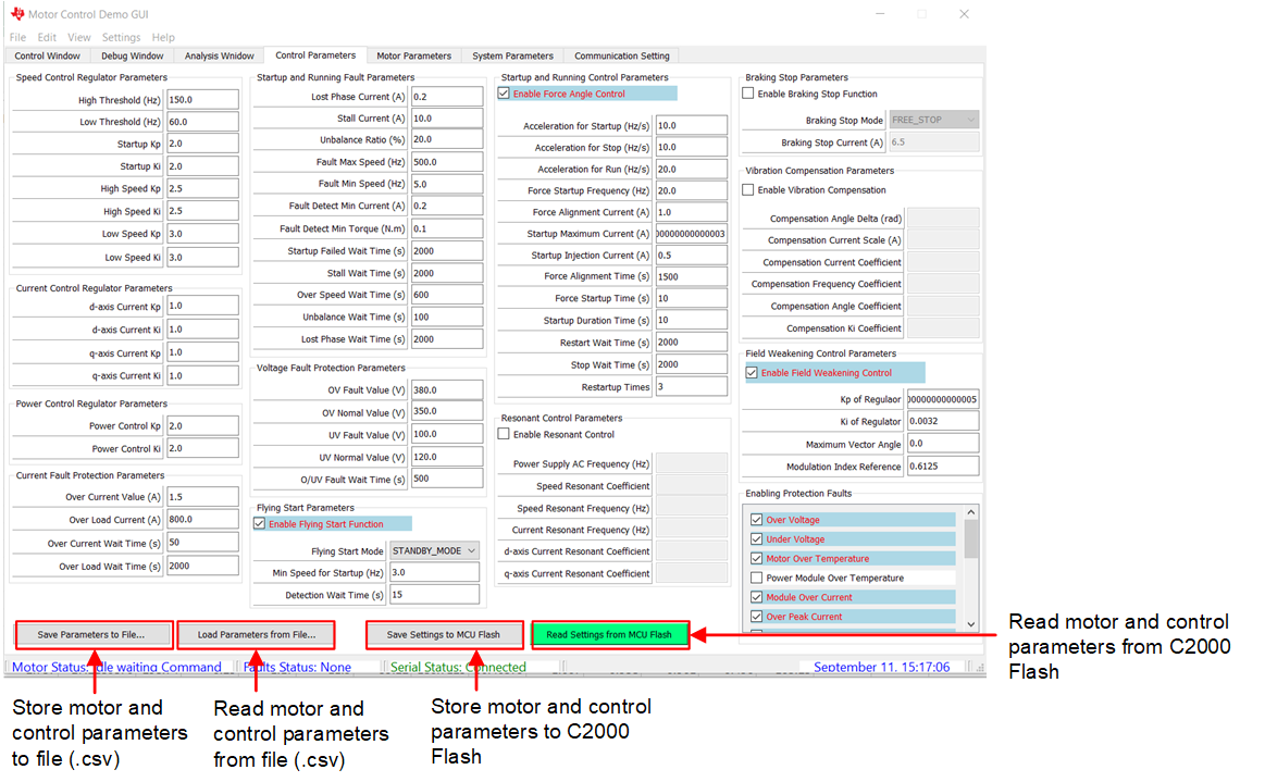
IdentificationAfter identification is complete, the Motor Pairs, Stator resistance, Stator inductance, flux, and so forth, must be written to MCU flash to make sure those parameters are saved inside the MCU. Select the Control Parameters tab, choose to store motor and control parameters to MCU Flash, or save them to a file. To verify writing is successful, click the Read Settings from MCU Flash button, then select the Motor Parameters tab to make sure motor parameters are the same as what were written before. Figure 3-9 shows the locations of the buttons mentioned in this paragraph.
 Figure 3-9 Store Motor Identification
Result