TIDUF78 May 2024
4.2 Test Setup
The following hardware equipment was used to evaluate this reference design.
| EQUIPMENT | COMMENT |
|---|---|
| TIDA-060045 | This reference design |
| LAUNCHXL-F280049C | F280049C LaunchPad™ development kit C2000™ Piccolo™ MCU |
| N45-1350 | Cylindrical disc magnet, 1350mT, 25mm diameter, 3mm height |
| LAUNCHXL-F28379D | F28379D LaunchPad™ development kit for C2000™ Delfino™ MCU |
| TIDA-010026 | Robust interface reference design for EnDat2.2 absolute encoders |
| Heidenhain LC 415 | EnDat2.2 absolute linear position encoder, accurate grade ± 5µm, 0.010µm resolution |
The test setup is shown in Figure 4-3 and Figure 4-4.
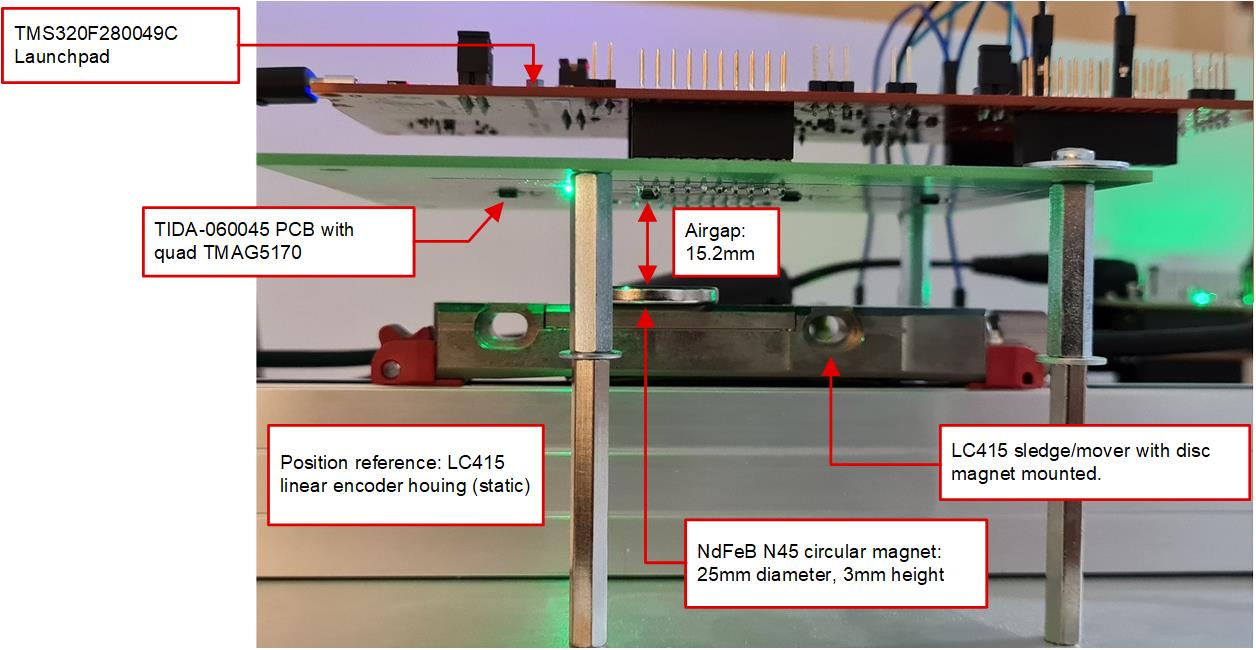
 Figure 4-3 Test Setup Side View
The above Figure 4-3 shows the side view of the test setup. A Heidenhain absolute linear encoder with EnDat2.2 and 320mm length is used as position reference and mounted on a fixed plate. The circular sense magnet is mounted on top of the moving sledge of the LC415 linear encoder. The sledge is connected to the EnDat2.2 interface cable and pulling the cable allows moving the position of the magnet. The TIDA-060045 PCB is mounted to the fixed plate on top of the LC415 linear encoder with the four TMAG5170 3D Hall-effect sensors facing downward. The center of each 3D Hall-effect sensor inside the TMAG5170 (y axis) is adjusted to the center of the moving magnet. The airgap (z-axis) between the top of the magnet and the Hall-effect sensor inside TMAG5170 is 15.2mm. The TMS320F280049C LaunchPad connects to the TIDA-060045 PCB through the headers J1, J3 and J2, J4. In this test setup, the TMS320F280049C LaunchPad provides the 3.3V supply to the TIDA-060045 too.
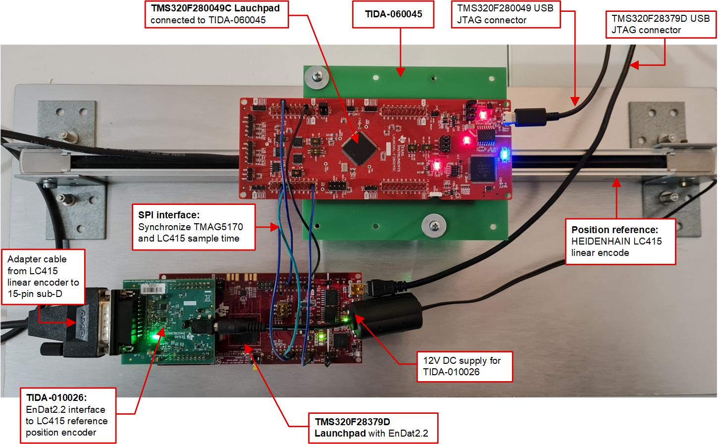
 Figure 4-4 Test Setup Top View
Figure 4-4 shows the top view of the test setup with the TIDA-060045 and the TMS320F280049C LaunchPad mounted on top of the LC415 linear position reference encoder as described before. The LC415 linear encoder connects to the TIDA-010026 EnDat2.2 reference design. The TIDA-010026 is powered from 12V and connected to a TMS320F28379D LaunchPad, which runs the EnDat2.2 software. Both LaunchPads are connected through SPI to synchronize the sampling time of the four TMAG5170 and the LC415 linear encoder and send the corresponding LC415 reference position at a sample rate up to 4kHz to the TMS320F280049C LaunchPad.
To validate this reference design a TI internal test software has been developed with the TMS320F280049C LaunchPad using the TMAG5170 header files TMAG5170-CODE-EXAMPLEand the C2000WARE software development kit for C2000 MCUs. For question on C2000WARE refer to the E2E™ design support for the C2000 microcontroller forum. For questions on the TMAG5170-CODE-EXAMPLE refer to thesensors forum.
The TI internal test software running on the TMS320F280049C has two operating modes. The real-time mode continuously measures the absolute linear position (x-axis) of the magnet mounted to the LC415 sledge at a 4kHz rate and calculates the corresponding position error. The trigger mode starts sampling a sequence of 200 positions after the magnet reaches a predefined absolute start position read from the LC415 reference encoder. Refer to the test results section for more details. This absolute start position is 12cm absolute and the 10 cm measurement range of the quad TMAG5170 begins at 13.2cm to 23.2cm absolute reference position. This is used for dynamic accuracy measurements, where the LC415 shuttle with the sensor magnet is moved accordingly and all the data is stored in memory. The data is read out through Code Composer Studio and validated with tools such as Excel and MATLAB®.
 Figure 4-5 Flowchart Linear Position Test
Software