TIDUF78 May 2024
4.3.2 Linear Position Measurement
As described in Section 3.2.4, the moving magnet position is calculated from the sensor with the highest Z-field magnitude using the Z- and X-field components. To adjust for the off-axis measurement the measured Z field was calibrated for gain and offset. In addition, a compensation factor multiplied by the absolute magnitude of the X field was used to compensate a nonlinearity with the position calculation. In addition, the displacement between each TMAG5170 on the PCB was corrected. For simplicity, the same value was used as distance between each TMAG5170.
| TMAG5170 | 1 | 2 | 3 | 4 |
|---|---|---|---|---|
| Z offset | 14.6mT | 14.3mT | 14mT | 13.8mT |
| Z gain | 0.94 | 0.93 | 0.94 | 0.94 |
| Displacement | 24.97mm | 24.97mm | 24.97mm | 24.97mm |
| X axis compensation factor | 0.001538 | 0.001538 | 0.001538 | 0.001538 |
The position was measured at a linear speed of around 0.4m/s at 22°C room temperature. The peaks observed at either end of the data capture are the result of the magnet leaving the sensing range of the quad sensor PCB.
 Figure 4-11 Linear Position Error Over
Quad TMAG5170 at Room Temperature
Figure 4-11 Linear Position Error Over
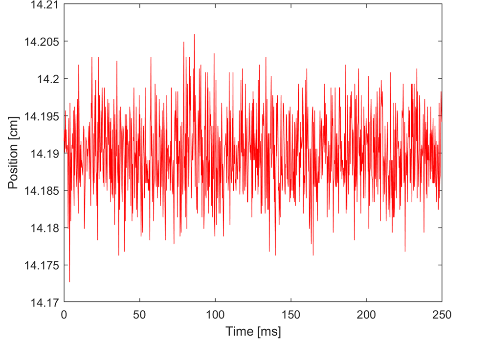
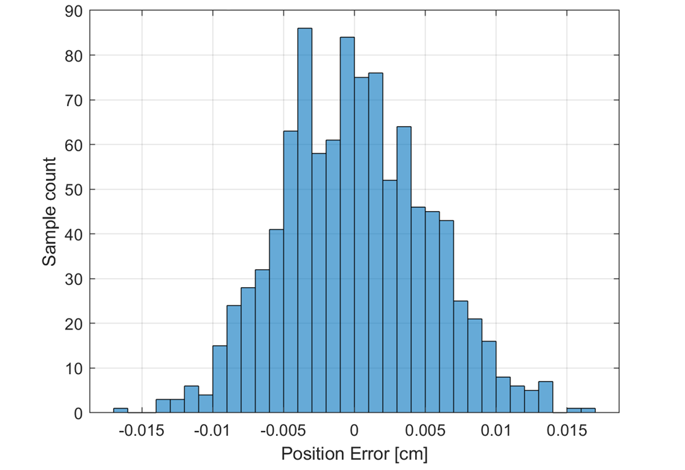
Quad TMAG5170 at Room TemperatureTo measure the impact of the Z field and X field noise floor, the static position error at 14.19cm was measured at over 1000 samples at 4kHz, as shown in Figure 4-11. The corresponding histogram is shown in Figure 4-12. Measurements are at 22°C room temperature.
 Figure 4-12 Static Position Over 1000
Samples at 4kHz Sample Rate
 Figure 4-13 Histogram of Position Error at
Magnet Position 14.19cm
Figure 4-13 Histogram of Position Error at
Magnet Position 14.19cmThe corresponding standard deviation and ENOB versus full-scale position measurement range are shown in Table 4-6.
| QUAD TMAG5170 | POSITION ERROR | COMMENT |
|---|---|---|
| Standard deviation [cm] | 0.0053 | |
| Full-scale range [cm] | 10 | quad 3D sensors |
| ENOB [bit] | 10.6 |
Each individual TMAG5170 provides an ENOB of 8.6-bit over the 2.5cm measurement range. Due to the quad TMAG5170 array with the 10cm range, the overall ENOB increase by 2-bit to the 10.6-bit shown in the table above.
Following that test, the position measurement was repeated 5 times at a linear speed of around 0.4m/s to outline the impact of the Z field and X field noise to the absolute accuracy. The test result is shown Figure 4-14.
 Figure 4-14 Linear Position Error Over 5
Test Runs
Figure 4-14 Linear Position Error Over 5
Test RunsFurther optimization is possible by more advanced compensation algorithms, see also. Magnets with higher field strength allow increase of the magnetic field strength to 100mT for the Z-axis and 50mT for the X-axis and help increase the signal to ratio by a factor of 2, respectively. Refer to Magnet Selection for Linear Position Applications (Rev. A).
A video demonstration of TIDA-060045 can be viewed at Designing with 3D Hall-effect sensors: Linear position encoding. For help simulating magnetic systems, the TI Magnetic Sense Simulator (TIMSS) tool can accelerate design and evaluation of magnetics systems.