TIDUF78 May 2024
5.1.3.2 Layout Guidelines
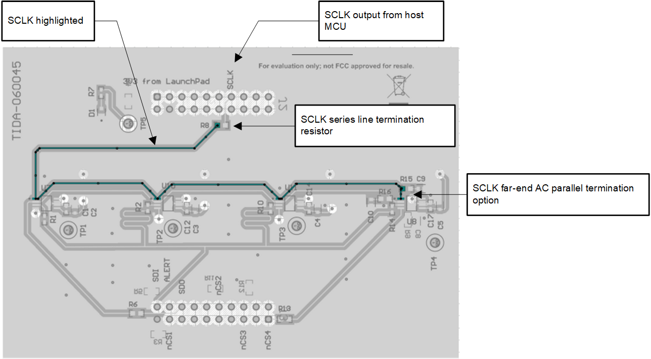
The layout of the SPI clock signal SCLK is shown in Figure 5-1. The SCLK is routed on the top layer in daisy chain from the first TMAG5170 (U7) to the last TMAG5170 (U8) with a serial line termination resistor and an optional far end AC parallel termination. The nALERT and the MOSI (TMAG5170 SDI) signals are routed the same way. A solid GND plane on the mid 1 layer below acts as a return GND.
 Figure 5-1 SPI Clock (SCLK) Trace
Routing
Figure 5-1 SPI Clock (SCLK) Trace
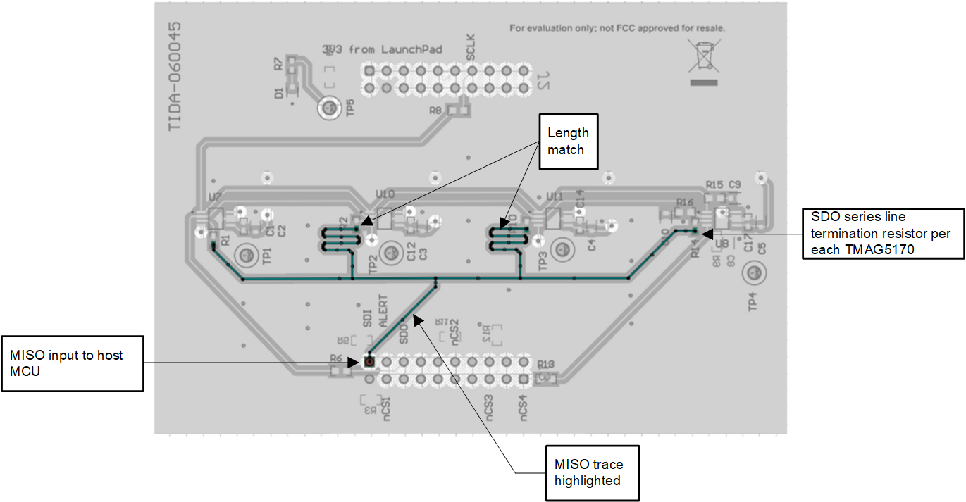
RoutingThe individual SDO output (SPI MISO) of each TMAG5170 has a serial line termination resistor. The four SDO traces from each TMAG5170 are star routed with similar length before being merged into a single trace to connect to the host processor MISO input pin.
 Figure 5-2 MISO Length Matched Star
Topology