TIDUF82A
August 2024 – November 2024
DRV8162
,
INA241A
,
ISOM8710
1
Description
Resources
Features
Applications
6
1
System Description
1.1
Reference Design Overview
1.2
Key System Specifications
2
System Overview
2.1
Block Diagram
2.2
Design Considerations
2.2.1
Hardware Design
2.2.1.1
Power Stage Gate Driver
2.2.1.1.1
Gate Driver
2.2.1.1.2
Protection Features
2.2.1.1.3
VGVDD Definition
2.2.1.1.4
Strap Functions
2.2.1.2
Power Stage FETs
2.2.1.2.1
VGS versus RDS(ON)
2.2.1.3
Phase Current and Voltage Sensing
2.2.1.3.1
Phase Current
2.2.1.3.2
Phase Current – Bias Voltage Reference
2.2.1.3.3
Voltage
2.2.1.4
Host Processor Interface
2.2.1.5
Gate Drive Shutdown Path
2.2.1.6
System Diagnostic Measurements
2.2.1.6.1
Temperature Measurement
2.2.1.7
System Power Supply
2.2.1.7.1
12V Rail
2.2.1.7.2
3.3V Rail
2.2.2
Software Design
2.3
Highlighted Products
2.3.1
DRV8162L
2.3.2
INA241A
2.3.3
LMR38010
2.3.4
TMP6131
2.3.5
ISOM8710
3
Hardware, Software Test Requirements and Test Results
3.1
Hardware Requirements
3.1.1
PCB Overview
3.1.2
Hardware Configuration
3.1.2.1
Prerequisites
3.1.2.2
Default Resistor and Jumper Configuration
3.1.2.3
Connector
3.1.2.3.1
Host Processor Interface
3.2
Test Setup
3.3
Test Results
3.3.1
Power Management
3.3.1.1
Power Up
3.3.1.2
Power Down
3.3.2
Gate Voltage and Phase Voltage
3.3.2.1
20 VDC
3.3.2.2
48 VDC
3.3.2.3
60 VDC
3.3.3
Digital PWM and Gate Voltage
3.3.4
Phase-Current Measurements
3.3.5
System Test Results
3.3.5.1
Thermal Analysis
4
Design and Documentation Support
4.1
Design Files
4.1.1
Schematics
4.1.2
BOM
4.2
Tools and Software
4.3
Documentation Support
4.4
Support Resources
4.5
Trademarks
5
About the Authors
6
Revision History
3.3.2.3
60 VDC
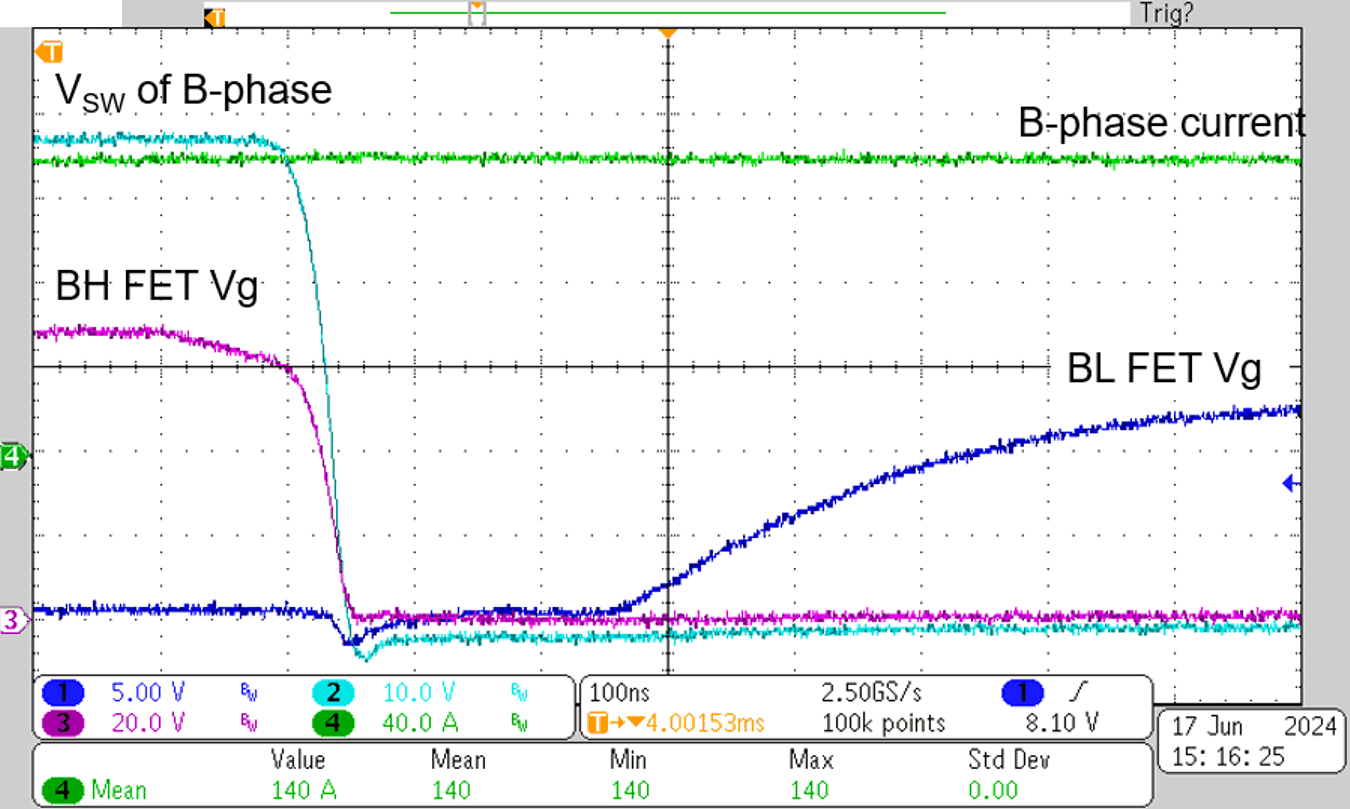
Figure 3-15
Hard Switching, Phase Current
at 60V, 140A
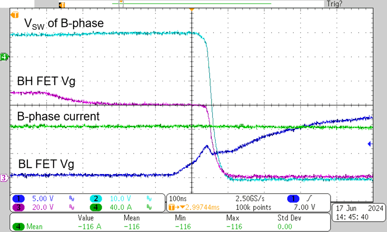
Figure 3-17
Soft Switching, Phase Current
at 60V, –116A
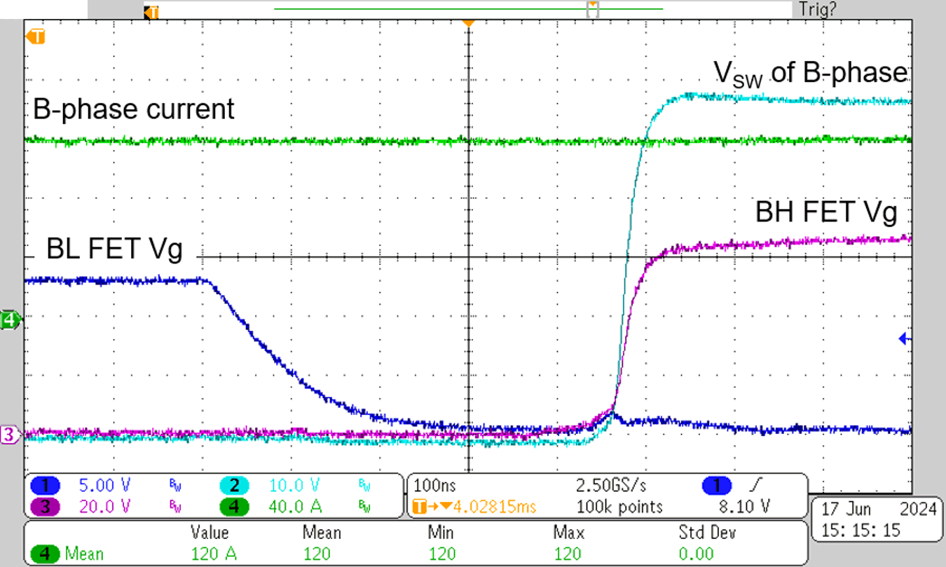
Figure 3-16
Soft Switching, Phase Current
at 60V, 120A
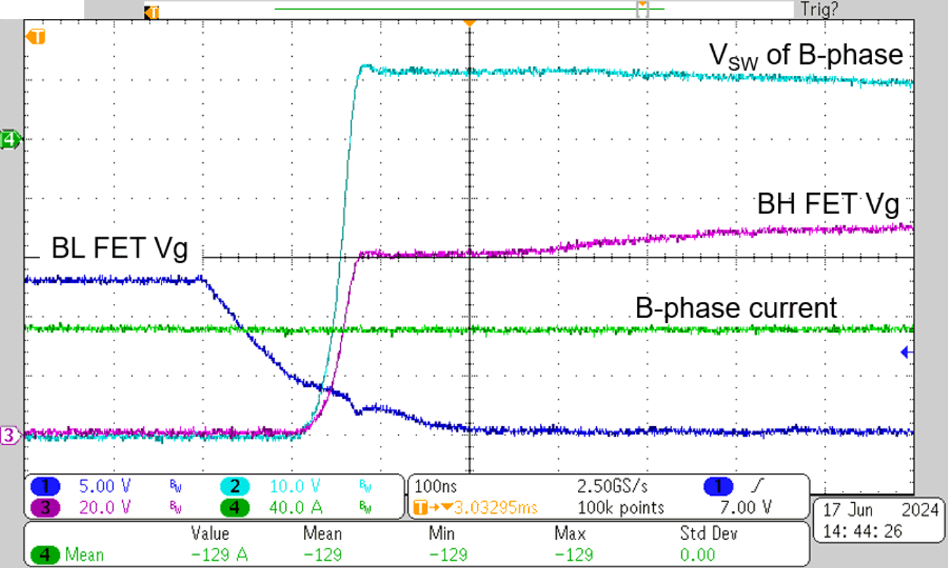
Figure 3-18
Hard Switching, Phase Current
at 60V, –129A