TIDUF84 June 2024
- 1
- Description
- Resources
- Features
- Applications
- 6
- 1System Description
- 2System Overview
- 3System Design Theory
- 4Hardware, Software, Testing Requirements, and Test Results
- 5Design and Documentation Support
- 6About the Author
- 7Recognition
4.1.2 TIDA-010951 PCB
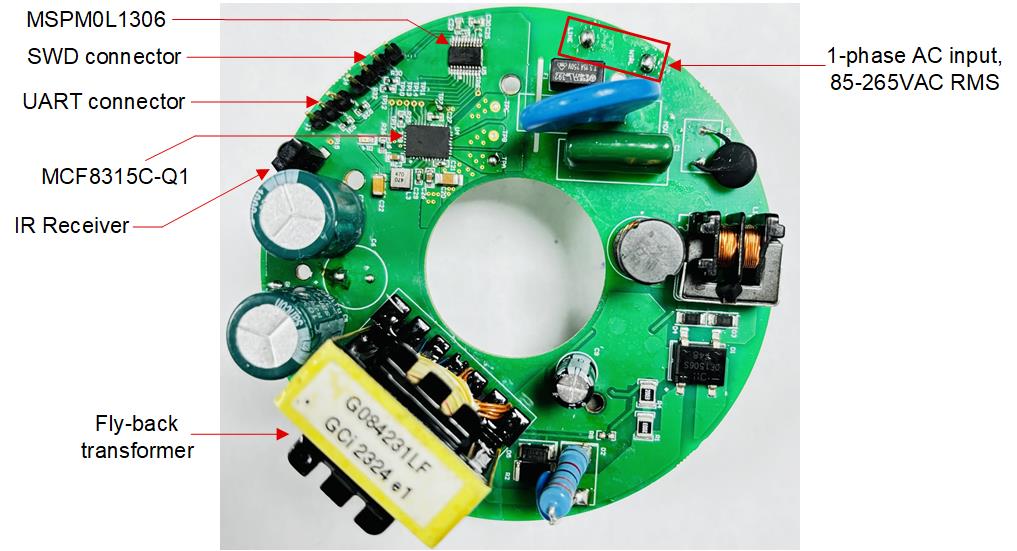
The TIDA-010951 requires only one power input: a 1-phase, 85-265VAC RMS source capable of delivering up to 50W. The input terminals for the AC power supply are on the top side of the PCB (highlighted in a box) in the top right quadrant of Figure 4-1. The diode rectifier, fly-back transformer and the 24V rail bus capacitors are also on the top side of the PCB. The BLDC motor driver MCF8315C is powered off the 24V rail and drives the BLDC motor based on the speed command received over I2C from an MCU (MSPM0L1306) shown in Figure 4-1. The IR receiver to receive the speed command is also on the top side of the PCB. In addition, the two connectors for communication with the MSPM0L1306 (SWD and UART) are also placed on the top side of the PCB as marked in Figure 4-1.
 Figure 4-1 TIDA-010951 PCB Top View
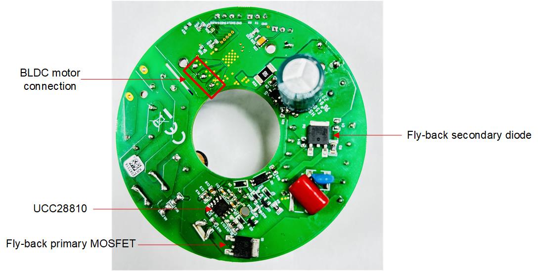
The PCB bottom side shows the fly-back converter components including the controller, UCC28810, primary MOSFET and secondary diode. In addition, the three phase outputs for the BLDC motor are also available on the bottom side of the PCB as marked in Figure 4-2.
 Figure 4-2 TIDA-010951 PCB Bottom
View