TIDUF84 June 2024
- 1
- Description
- Resources
- Features
- Applications
- 6
- 1System Description
- 2System Overview
- 3System Design Theory
- 4Hardware, Software, Testing Requirements, and Test Results
- 5Design and Documentation Support
- 6About the Author
- 7Recognition
4.4 Test Setup
- Make familiar with the TIDA-010951 PCB, schematic and layer plots. Remember that the TIDA-010951 PCB and related interfaces can be exposed to high voltages
- Test and validate the TIDA-010951 PCB only in a proper lab. Verify the TIDA-010951 PCB is de-energized and not connected to any power supply before handling the PCB, making any power or signal connections for measurement and more.
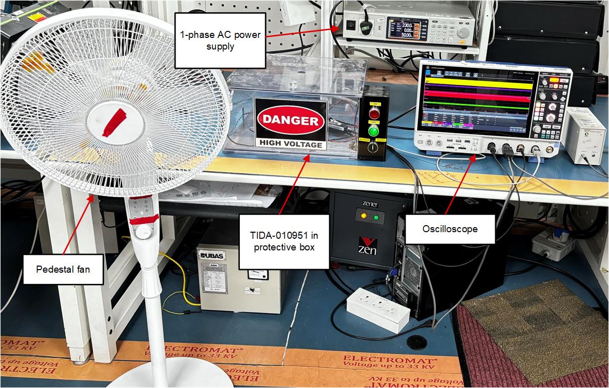
- Place the TIDA-010951 in a protective box with emergency stop button to turn off the input power quickly in case of emergency.
- Use fans with appropriate guards to protect from spinning fan blades.
- Use properly rated connectors to connect the 1-phase AC power input to TIDA-010951.
- Fan speed control can be achieved by two methods – using ‘Analog’ speed control mode and a (0-3)V input to SPEED pin of MCF8315C or using ‘I2C’ speed control mode and sending speed command through MSPM0L1306.
- Speed control through IR remote can also be achieved using the IR receiver and proper IR protocol implementation on MSPM0L1306.
 Figure 4-3 Picture of Test Setup