TIDUF84 June 2024
- 1
- Description
- Resources
- Features
- Applications
- 6
- 1System Description
- 2System Overview
- 3System Design Theory
- 4Hardware, Software, Testing Requirements, and Test Results
- 5Design and Documentation Support
- 6About the Author
- 7Recognition
4.5.2 UCC28810 Based Single Stage PFC
TIDA-010951 provides a UCC288210 based secondary side regulated single stage PFC that generates an isolated 24V rail capable of delivering up to 2A. This fly-back converter can operate across (140-265) VAC RMS and provide a tightly regulated 24V while maintaining an input power factor (PF) > 0.92 and input current THD < 12.5% at 35W load (from 24V). The line, load regulation, efficiency, input PF and THD of the single stage PFC is as shown in Table 4-2.
Vin (AC RMS) | PIN (W) | POUT (W) | VOUT (V) | Efficiency (%) | Input PF | Input current THD (%) |
|---|---|---|---|---|---|---|
140 | 8.49 | 6 | 24.15 | 70.68 | 0.867 | 26.5 |
14.38 | 11 | 24.16 | 76.5 | 0.964 | 10.51 | |
21.19 | 17 | 24.15 | 80.23 | 0.978 | 9.65 | |
30.35 | 25 | 24.16 | 82.38 | 0.985 | 10.1 | |
42 | 35 | 24.15 | 83.34 | 0.988 | 11.5 | |
230 | 8.49 | 6 | 24.15 | 70.68 | 0.51 | 45.43 |
14.34 | 11 | 24.15 | 76.71 | 0.682 | 36 | |
21.25 | 17 | 24.15 | 80 | 0.826 | 22.5 | |
30.48 | 25 | 24.16 | 82.03 | 0.93 | 10.4 | |
42 | 35 | 24.15 | 83.34 | 0.95 | 9.6 | |
265 | 8.6 | 6 | 24.15 | 69.77 | 0.426 | 45.1 |
14.45 | 11 | 24.15 | 76.13 | 0.579 | 40.4 | |
21.32 | 17 | 24.15 | 79.74 | 0.709 | 32.67 | |
30.47 | 25 | 24.15 | 82.05 | 0.828 | 20.9 | |
42.04 | 35 | 24.16 | 83.26 | 0.92 | 12.2 |
If you want to use TIDA-010951 at 85VAC-140VAC, we need to make some modifications to the PCB to achieve good PF and iTHD.
Please check following changes and test results in Table 4-2.
R14=6.8Kohm, R19=DNP, R17=0.22ohm, R18=2.2Kohm, C16=47pF, R20=18Kohm.
| Vin (AC RMS) | PIN (W) | POUT (W) | VOUT (V) | Efficiency (%) | Input PF | Input current THD (%) |
|---|---|---|---|---|---|---|
| 85 | 8.49 | 6 | 24.11 | 78.9 | 0.968 | 8.5 |
| 14.38 | 11 | 24.11 | 83.9 | 0.977 | 9.4 | |
| 21.19 | 17 | 24.11 | 84.8 | 0.961 | 9.4 | |
| 30.35 | 25 | 24.11 | 85.5 | 0.949 | 11.9 | |
| 42 | 35 | 24.11 | 85.2 | 0.948 | 12.0 | |
| 110 | 8.49 | 6 | 24.11 | 78.9 | 0.94 | 14.9 |
| 14.34 | 11 | 24.11 | 84.0 | 0.964 | 9.3 | |
| 21.25 | 17 | 24.11 | 88.6 | 0.965 | 9.6 | |
| 30.48 | 25 | 24.11 | 87.1 | 0.955 | 10.8 | |
| 42 | 35 | 24.11 | 87.0 | 0.951 | 11.6 | |
| 140 | 8.6 | 6 | 24.11 | 77.9 | 0.86 | 21.1 |
| 14.45 | 11 | 24.1 | 83.0 | 0.941 | 10.6 | |
| 21.32 | 17 | 24.11 | 84.8 | 0.952 | 9.6 | |
| 30.47 | 25 | 24.11 | 87.0 | 0.961 | 10.0 | |
| 42.04 | 35 | 24.11 | 87.3 | 0.956 | 10.5 |
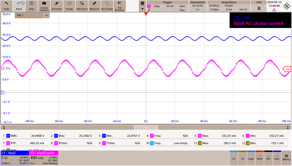
Figure 4-4 shows the input phase current while delivering 35W (drawn from 24V rail) at 230V RMS. The input power factor is 0.95 and input current THD is 9.6%.
 Figure 4-4 Input Phase Current at 230V RMS, 35W Load (Drawn From 24V Rail)