TIDUF87 November 2024
- 1
- Description
- Resources
- Features
- Applications
- 6
- 1System Description
- 2System Overview
-
3Hardware, Software, Testing Requirements, and Test Results
- 3.1 Hardware Requirements
- 3.2 Software Requirements
- 3.3 Test Setup
- 3.4
Test Procedure
- 3.4.1 Lab Variables Definitions
- 3.4.2 Lab 1. Open-Loop Current Control Single Phase
- 3.4.3 Lab 2. Closed Loop Current Control Single Phase
- 3.4.4 Lab 3. Open Loop Voltage Control Single Channel
- 3.4.5 Lab 4. Closed Loop Current and Voltage Control Single Channel
- 3.4.6 Lab 5. Closed Loop Current and Voltage Control Four Channels
- 3.4.7 Calibration
- 3.5 Test Results
- 4Design and Documentation Support
- 5About the Author
3.4.3.1 Setting Software Options for Lab 2
- To run this lab, make sure the hardware is set up as outlined in the previous section, Figure 3-9
- Open the CCS project as outlined in Section 3.2.1. If using the powerSUITE, go to Step 3, otherwise, jump to Step 4.
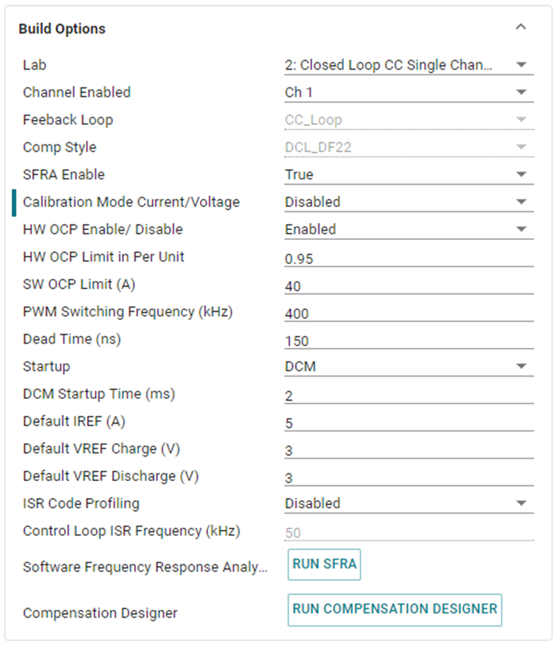
- Open the SYSCONFIG page and select under the Build Options section:
- Select Lab 2: Closed Loop CC Single Channel for the Lab
- Select the Channel
- Enable the SFRA
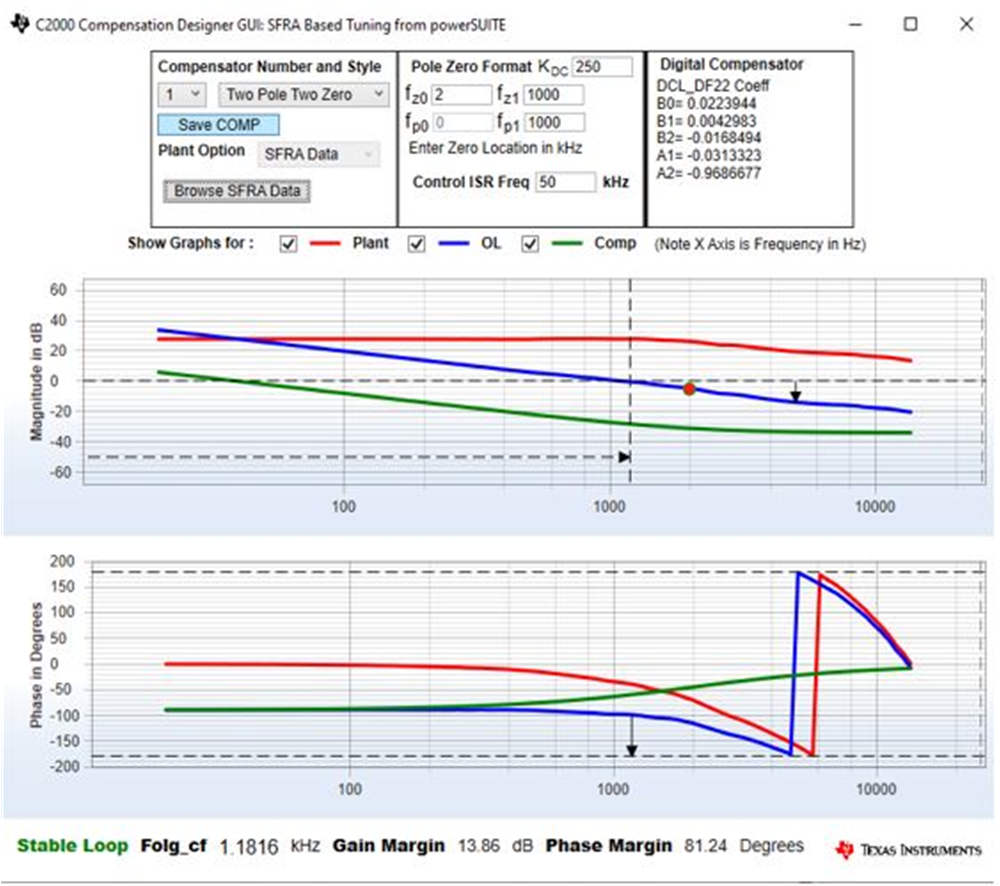
- Open the Compensation Designer
 by clicking the Run Compensation Design button.
 - The compensation designer then launches and prompts the user to select a valid SFRA data file. Import the SFRA data from the run in Lab 1 into the compensation designer to design a two-pole, two-zero compensator. Keep more margins during this iteration of the design to make sure that when the loop is closed, the system is stable.
- Figure 3-18 shows compensation parameters for the Current Loop.
- Click on the Save Comp button to save the compensation. Close the Compensation Designer tool.
- Save the SYSCONFIG page.
- When using non-powerSuite version of the project,
Build Settings are directly modified in
solution_settings.hfile. Compensation Designer is found atC2000Ware_DigitalPower_Install_Location\powerSUITE\source\utils.#define LAB_NUMBER (2) #define CHANNEL_NUMBER (1) #define SFRA_ENABLED (true)
 Figure 3-17 Build Options for Lab
2
 Figure 3-18 Tuning Current Loop Using
Compensation Designer