TIDUF89 September 2024
- 1
- Description
- Resources
- Features
- Applications
- 6
- 1System Description
- 2System Overview
- 3Hardware, Software, Testing Requirements, and Test Results
- 4Design Files
- 5Tools and Software
- 6Document Support
- 7Support Resources
- 8Trademarks
- 9About the Authors
3.3 Test Setup
TI recommends conducting the following series of tests to evaluate the performance of the radar for maximum range, low power consumption and minimal false alarm rate.
Table 3-1 Radar Surveillance Test Suite
| Test ID | Test Name | Parameter Under Test | Results |
|---|---|---|---|
| 1 | Detection Range | Detection at long range | Detection Distance in meters |
| 2 | Empty Scene False Alarm Rate | Low False Alarm Rate | Percentage of time in each mode, number of false alarms |
| 3 | Power Consumption | Power Consumption | Power Consumption in mW |
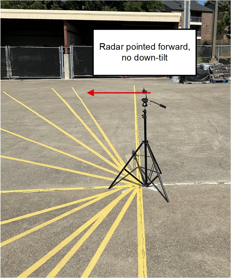
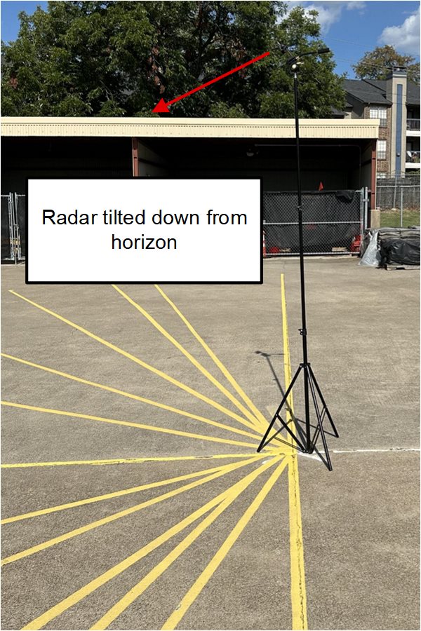
In each test, TI recommends mounting the radar as the radar is intended for operation, which can be at different heights and angles. Two common installations are a doorbell configuration, where the device is placed about one meter high and angled straight out to the horizon, and a video camera configuration, where the device is mounted higher and tilted slightly down to increase the camera's field of view.

Figure 3-1 Radar Mounting Doorbell Configuration

Figure 3-2 Radar Mounting Camera Configuration