TIDUF91 December   2024


  1.   1
  2.   Description
  3.   Resources
  4.   Features
  5.   Applications
  6.   6
  7. 1System Description
    1. 1.1 Key System Specifications
  8. 2System Overview
    1. 2.1 Block Diagram
    2. 2.2 Design Considerations
    3. 2.3 Highlighted Products
      1. 2.3.1 DRV3901-Q1
  9. 3System Design Theory
  10. 4Hardware, Software, Testing Requirements, and Test Results
    1. 4.1 Hardware Requirements
    2. 4.2 Software Requirements
    3. 4.3 Test Setup
      1. 4.3.1 Hardware Setup
      2. 4.3.2 USB2ANY Explorer Setup
    4. 4.4 Test Results
  11. 5Design and Documentation Support
    1. 5.1 Design Files
      1. 5.1.1 Schematics
      2. 5.1.2 BOM
      3. 5.1.3 PCB Layout Recommendations
        1. 5.1.3.1 Layout Prints
    2. 5.2 Tools and Software
    3. 5.3 Documentation Support
    4. 5.4 Support Resources
    5. 5.5 Trademarks
  12. 6About the Author

Test Results

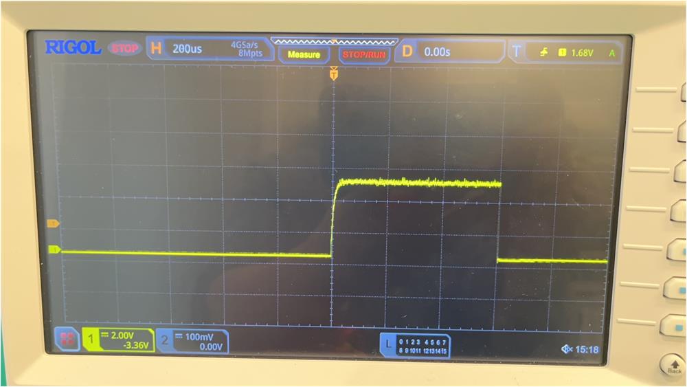
When the test setup is ready, write the deploy command, 3C 84 D8, the pyro-fuse is triggered (only when using the real pyro-fuse), and a trigger waveform can be obtained on the oscilloscope. Figure 4-8 illustrates the test result. The chip is supposed to deploy for approximately 2ms with the current limited to 1.2A, which is as expected.
TIDA-020075 TIDA-020075 Test ResultFigure 4-8 TIDA-020075 Test Result