TIDUF96 October 2024
3.1.1.4 AWRL1432 Initialization: Board Programming
Once the board is powered with the 12V connection, a program must be loaded into the external flash. The radar toolbox provides the application binaries, chirp configuration, and GUI to run the Kick-to-Open demonstration (see Section 3.2 for more details). TI also provides the mmWave low-power Software Development Kit (L-SDK). This is a unified software platform for the AWRLx family of mmWave sensors, which enable evaluation and development. The use of this design environment is covered in the mmWave Radar Visualizer User's Guide. Use the following steps for loading an application image file:
- Install the UniFlash software, which is available for download at: http://www.ti.com/tool/uniflash. Proceed to the next step after installation.
- Connect the board with the PC using either of the power up options mentioned in Section 3.1.1.1 or Section 3.1.1.2.
- Open the UniFlash software. Select
mmWave from the Category header,
select AWRL1432 from the field of available devices,
and then click the Start button (see Figure 3-3).
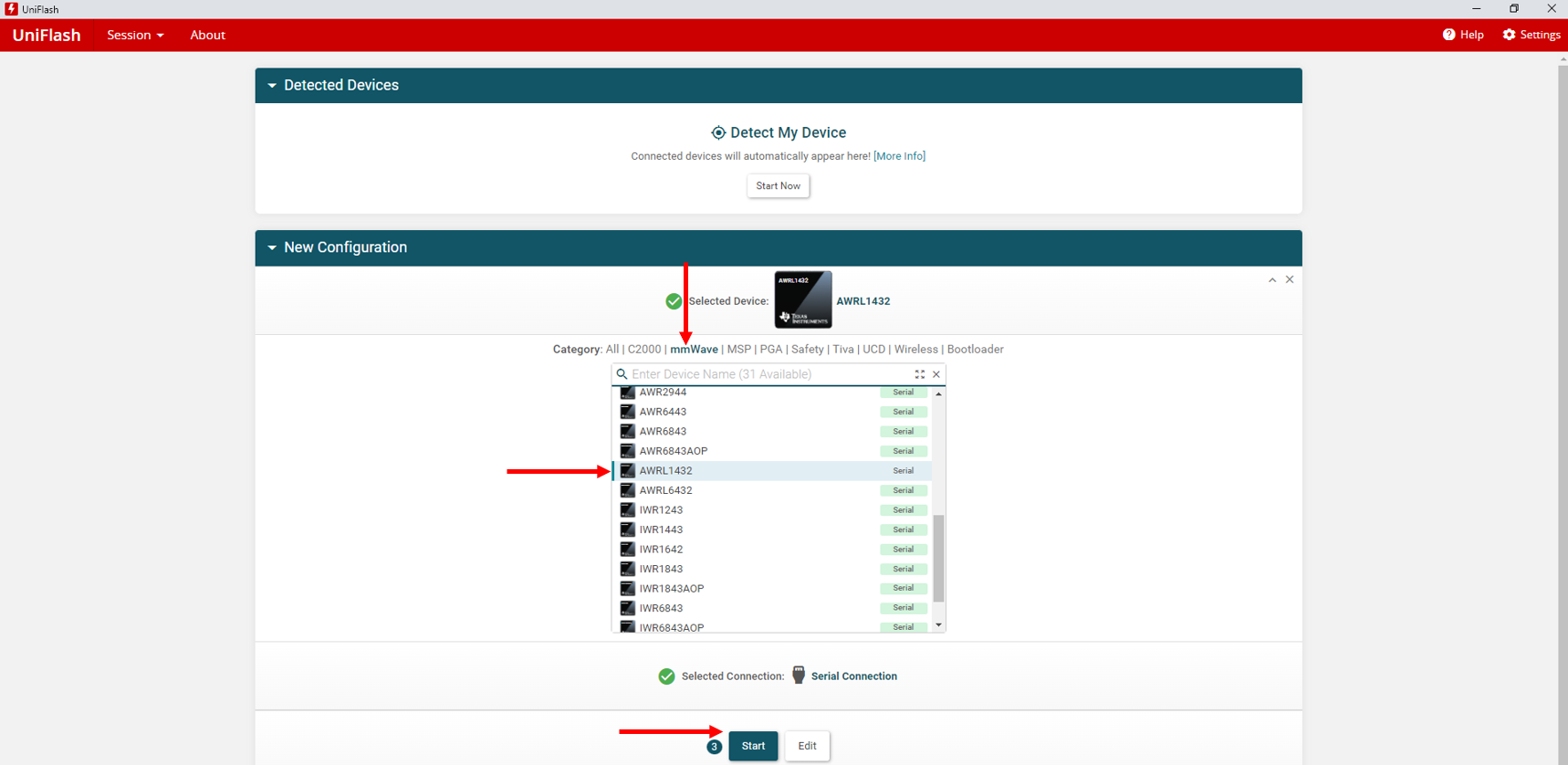
Figure 3-3 UniFlash Configuration - Click the
Browse button and navigate to the application
image file to load. The file path and name is
<RADAR_TOOLBOX_INSTALL_DIR>\radar_toolbox
                                                latest
                                                version\source\ti\examples\Kick_to_Open\prebuilt_binaries\gesture_recognition_demo.Release.appimage
. After the name of the file populates the field, click on the Settings & Utilities menu on the left side of the program (see Figure 3-4).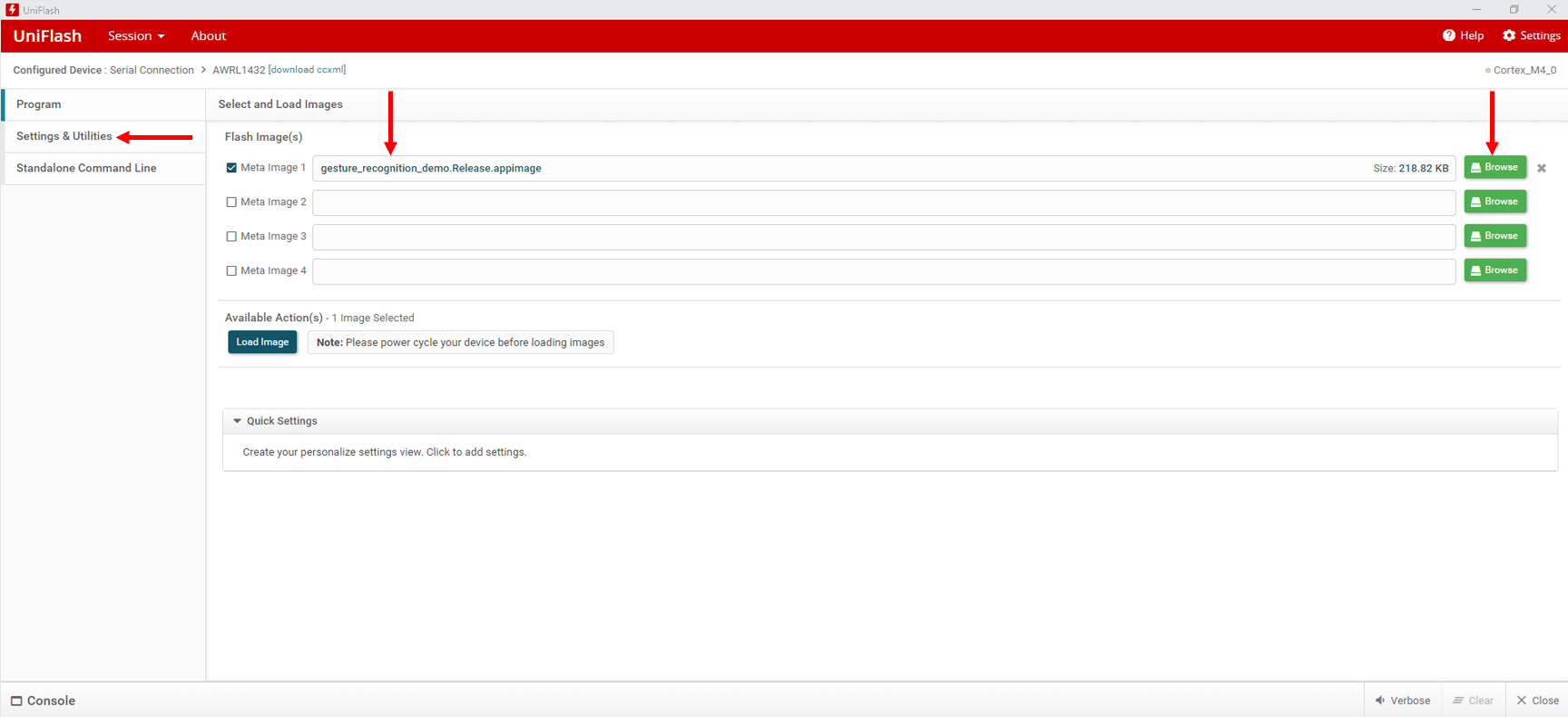
Figure 3-4 UniFlash Settings - After connecting the
LP-XDS110 into the USB port, open the Microsoft®
Windows®
Device Manager. Find the XDS110 Class
Application/User UART port and note the COM port
number. The example in Figure 3-5 shows this COM port to be COM20.
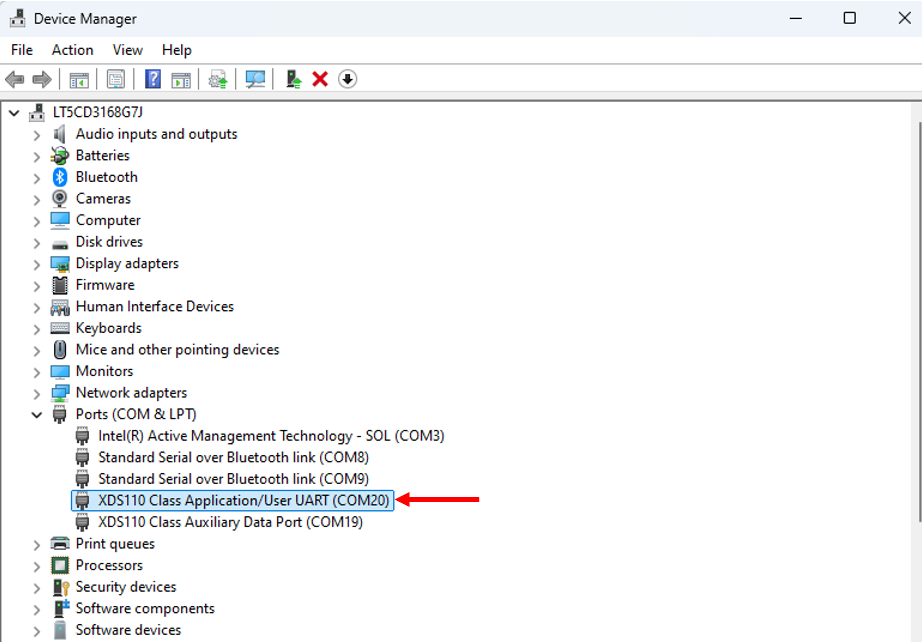
Figure 3-5 Determine COM Port - Return to the UniFlash
software and enter the noted COM port number from the device
manager. Then click the Program menu on the left side
of the window to go back to the previous menu (see Figure 3-6).
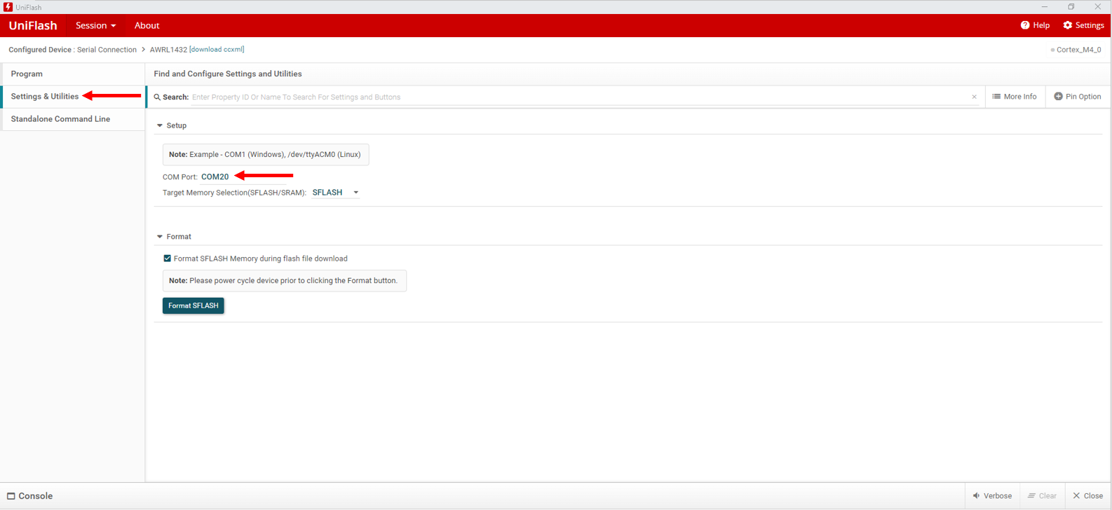
Figure 3-6 Enter COM Port - Reset the AWRL1432 device by pressing the reset button on the LP-XDS110. Then select Load Image. This action loads the program into the flash. To execute the program, change the SOP settings into functional mode. The program then runs.
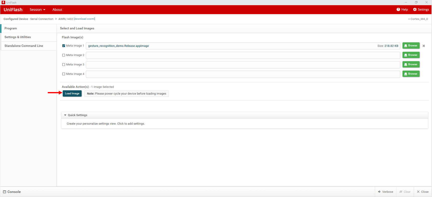
Figure 3-7 Load Image