TIDUF96 October   2024


  1.   1
  2.   Description
  3.   Resources
  4.   Features
  5.   Applications
  6.   6
  7. 1System Description
    1. 1.1 Key System Specifications
  8. 2System Overview
    1. 2.1 Block Diagram
    2. 2.2 Design Considerations
      1. 2.2.1 Power Topology
      2. 2.2.2 PCB and Form Factor
      3. 2.2.3 Antenna
    3. 2.3 Highlighted Products
      1. 2.3.1 AWRL1432BGAMFQ1
      2. 2.3.2 TPS628502-Q1
      3. 2.3.3 LMR43620-Q1
      4. 2.3.4 TLIN1021A-Q1
  9. 3Hardware, Software, Testing Requirements, and Test Results
    1. 3.1 Hardware Requirements
      1. 3.1.1 Getting Started With Hardware
        1. 3.1.1.1 Primary Power Up Option
          1. 3.1.1.1.1 Making the Connections in Primary Power Up Option
        2. 3.1.1.2 Secondary Power Up Option
          1. 3.1.1.2.1 Making the Connections in Secondary Power Up Option
        3. 3.1.1.3 Sense-on-Power (SOP)
        4. 3.1.1.4 AWRL1432 Initialization: Board Programming
    2. 3.2 Test Setup
    3. 3.3 Test Results
  10. 4Design and Documentation Support
    1. 4.1 Design Files
      1. 4.1.1 Schematics
      2. 4.1.2 BOM
      3. 4.1.3 Layout Prints
      4. 4.1.4 Altium Project
      5. 4.1.5 Gerber Files
    2. 4.2 Tools and Software
    3. 4.3 Documentation Support
    4. 4.4 Support Resources
    5. 4.5 Trademarks
  11. 5About the Authors

Antenna

This reference design includes onboard etched-patch antennas for the two receivers and two transmitters. This antenna design provides a wide Field of View (FOV) in azimuth with good gain and bandwidth coverage. Figure 2-5 shows the antenna design.
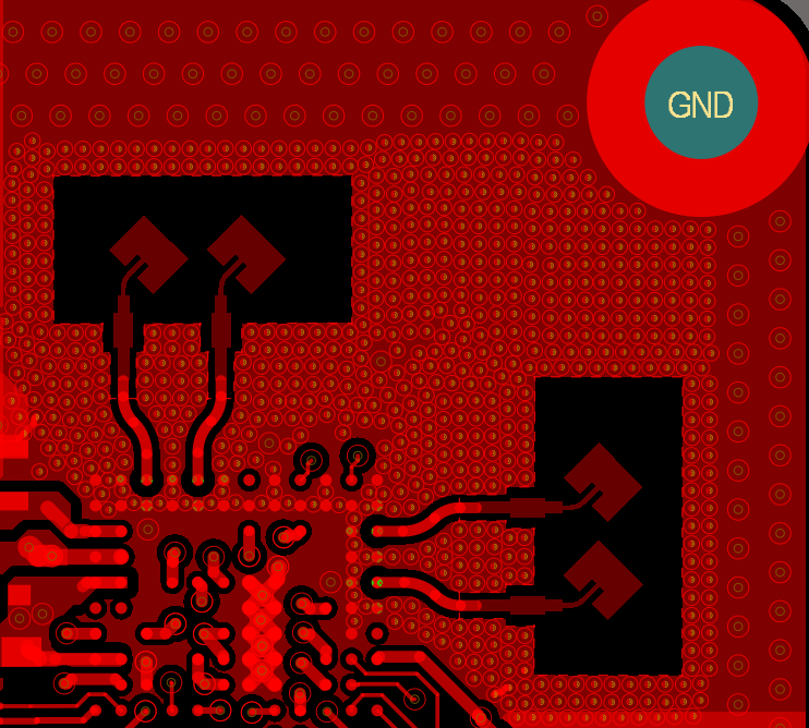
TIDEP-01036 Altium Antenna Design Figure 2-5 Altium Antenna Design

The antenna peak gain is greater than 4dBi across the operating frequency band of 76GHz to 81GHz. The performance parameters are listed in Performance Table.

Table 2-1 Performance Table
Parameters Values
Gain > 4dBi
FOV 120°(Azimuth) × 90°(Elevation)
Bandwidth 4.5GHz

Figure 2-6 shows the radiation pattern of one of the antenna elements in the horizontal plane (in red, Phi = 0°) and vertical plane at 79GHz (in green, Phi = 90°).
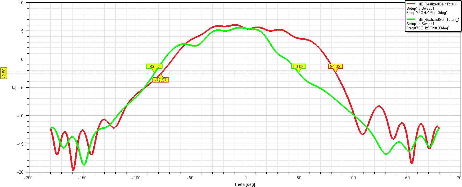
TIDEP-01036 Antenna Pattern Figure 2-6 Antenna Pattern