TIDUFB1 December 2024
- 1
- Description
- Resources
- Features
- Applications
- 6
- 1System Description
-
2System Overview
- 2.1 Block Diagram
- 2.2 Design Considerations
- 2.3 Highlighted Products
- 2.4
Hardware Design
- 2.4.1 Inductor Design
- 2.4.2 Bus Capacitor Selection
- 2.4.3 Input AC Voltage Sensing
- 2.4.4 Output DCBUS Voltage Sensing
- 2.4.5 Auxiliary Power Supply
- 2.4.6 Isolated Power Supply
- 2.4.7 Inductor Current Sensing
- 2.4.8 Gate Driver
- 2.4.9 Isolated Temperature Sensing
- 2.4.10 Overcurrent, Overvoltage Protection (CMPSS)
-
3Hardware, Software, Testing Requirements, and Test Results
- 3.1 Hardware Requirements
- 3.2
Software Requirements
- 3.2.1 Getting Started GUI
- 3.2.2
Getting Started Firmware
- 3.2.2.1 Opening the Project Inside Code Composer Studio™
- 3.2.2.2 Project Structure
- 3.2.2.3 Test Setup
- 3.2.2.4 Running Project
- 3.3
Test Results
- 3.3.1 IGBT Gate Rising and Falling Time
- 3.3.2 Power On Sequence
- 3.3.3 PFC Started by GUI
- 3.3.4 Zero Crossing Under 380VAC, 9kW
- 3.3.5 Current Ripple Under 380VAC,10kW
- 3.3.6 10kW Load Test With Grid Power
- 3.3.7 9kW Load Test With AC Power Source
- 3.3.8 Power Analyzer Results
- 3.3.9 Thermal Performance
- 3.3.10 Voltage Short Interrupt Test
- 3.3.11 Efficiency, iTHD, and Power Factor Results
- 4Design and Documentation Support
- 5About the Author
3.1.1.1 Board Overview
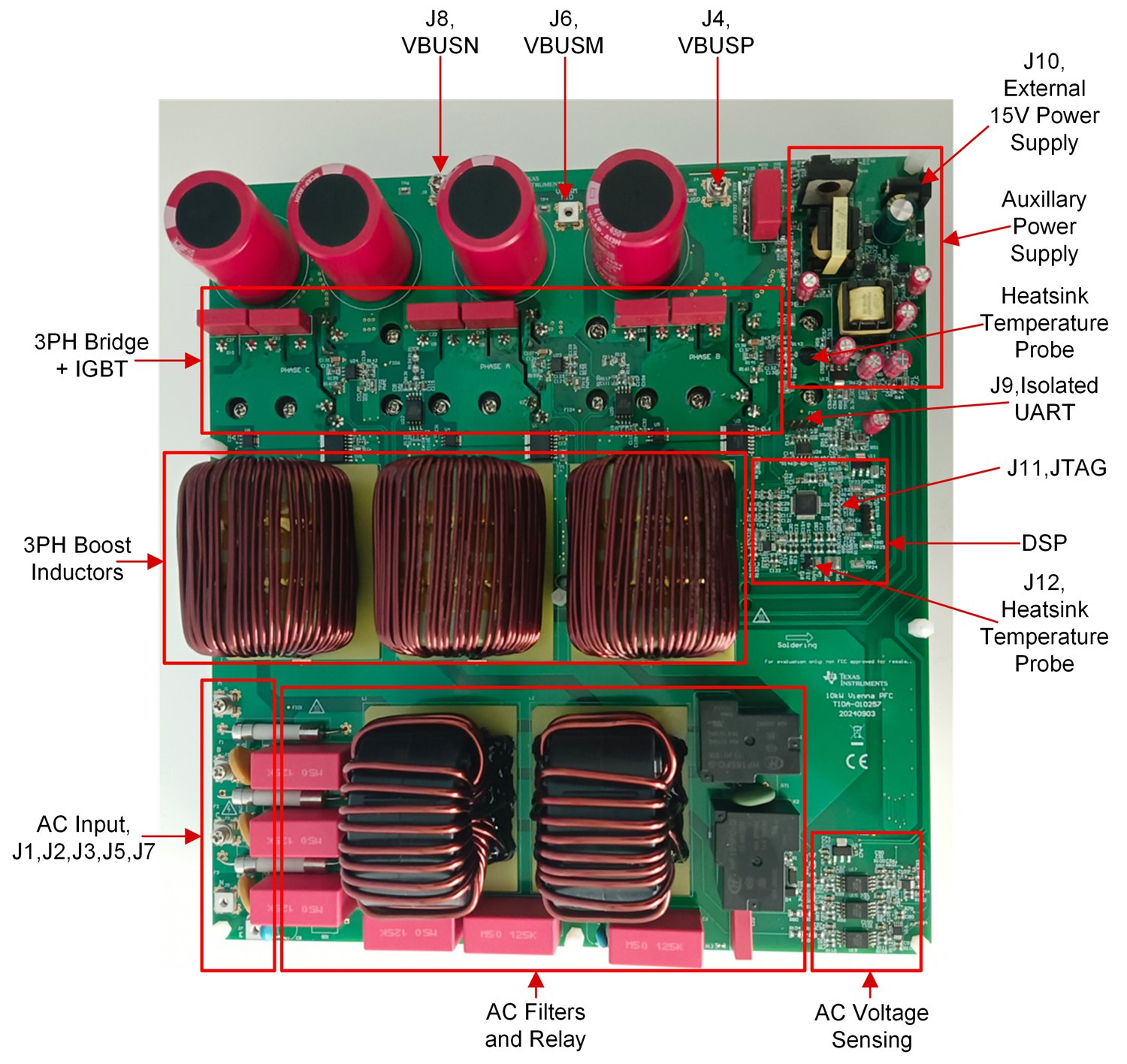
The reference board has functional groups that enable a complete three-phase Vienna PFC system. The following list show the function blocks on the board. Figure 3-1 shows the top view of the board and different blocks. Table 3-1 shows the key connectors and functions.
- AC input line filters and relays
- Boost Inductors
- Bridge and IGBTs
- Auxiliary power supply and isolated power supply
- DSP, F2800137
- Voltage sensing and gate drivers
- IGBT gate drivers
 Figure 3-1 Board Overview
Table 3-1 Key Connectors and Function
| CONNECTOR NAME | FUNCTION |
|---|---|
| J1, J2, J3 | Lines of three phase AC input |
| J5 | Neutral of three phase AC input |
| J7 | Ground of three phase AC input |
| J4 | Output DCBUS positive |
| J6 | Output DCBUS middle |
| J8 | Output DCBUS negative |
| J9 | Isolated universal asynchronous receiver-transmitter (UART) for GUI |
| J10 | 15V, 1A external power supply |
| J11 | cJTAG for debugging |
| J12 | Heat sink thermistor |