Reed Switch Replacement with TI's Hall-effect and Linear 3D Hall-effect Sensors
Trademarks
All trademarks are the property of their respective owners.
1 Introduction
Door and window sensors make up the backbone of any home security system and are specifically intended to monitor which doors and windows are opened and closed within a home or office. These devices are mostly battery operated and communicate with a main security system hub with information as to whether a door or window is open/closed. If an event occurs in which a door or window gets opened or breached when the alarm is on, the sensor sends an alert signal to the main control panel and immediately triggers the main alarm.
If we dive deeper into the internal workings of the door/window sensor, there is one device that is clearly integral to the functionality of this device, a ferromagnetic sensitive device. This can be a simple Reed switch or a Hall Effect sensor, but which is better for your design and why?
The subsequent sections of this article provide an overview of the common Reed Switch, the DRV5032, and the TMAG5170 in addition to a test/result based comparison with respect to performance and tamper susceptibility.
2 Reed Switch Overview
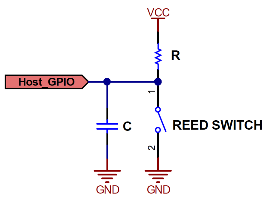
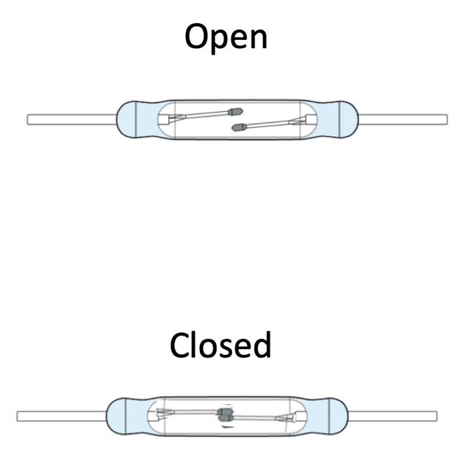
The Reed switch is probably one of the most prevalent components found in today’s door and or window sensor. The switch is essentially a glass tube filled with inert gas with two small blades comprised of some ferromagnetic material. These devices can come in N.O. (normally open) and N.C. (normally closed) configurations, but for much of the building security industry, the normally open contacts are the most popular choice. A common Reed switch is shown in Figure 2-1 along with a simple circuit that leverages the switch in a manner suitable for our application.
 |
 |
There are also post-production problems that occur with the use of a Reed switch that can be of concern. One major concern can be the limited lifetime of the Reed Switch. Because of the mechanical nature of this device, the lifetime of the device is limited due to natural wear and tear of the physical switch.
Another issue can be power consumption on the Reed switches depending on the peripheral circuitry used. If the switch is pulled up to a source voltage when the switch is open, there will be a current associated with this pull-up network. In other configurations, there will be a small current through a pull-down or pull-up resistor when the switch is closed. There are however configurations that can be used to minimize this consumption. These are listed below:
- It can be a sampling of the pull-up resistor. This means the voltage the pull-up is tied up to is controllable. Typically, an IO pin turned on for a few µs while another IO checks the voltage across the Reed switch.
- It can also be a more complex circuit using capacitor and other circuitry to avoid constant current consumption.
- It can also be a 3 terminal Reed switch. In that case the power consumption can be 0.
3 Hall Effect Sensor Overview
Hall effect sensors, unlike Reed switches, are IC devices that can also be used to detect magnetic fields. Some of the Hall Effect sensors Texas Instruments offers, such as the TMAG5273 and the TMAG5170, can even provide 3D spacial magnetic sensing with a linear output. Others offer a binary output just as the Reed switch when a magnetic field is detected on a particular axis. If we were to use a DRV5032 with a 1.8 V supply voltage on VCC and 5 samples per second, the average current consumption would be only 540nA which provides a great low-power option for Reed switch replacement.
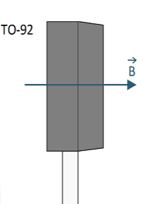
Hall Effect sensors detect the voltage difference (V) that develops on a conductor carrying an electrical current (I) in the presence of a magnetic field (B) as shown in Figure 3-1.
 |
 |
By integrating this electrophysical property into an IC, the magnetic field can be detected just as with the Reed switch. If we look at the DRV5032 schematic below, we see an example of this application leveraging a microcontroller to detect the binary output from the device. The distance of detection can be adjusted through the available magnetic threshold sensitivity variations of the product. For the testing included within this paper, we are using the omni-polar FB version of the device in a TO-92 package. More specific information on this device can be found on the DRV5032 product page on TI.com. Hall-effect switches such as the DRV5032 are suitable for applications where a simple open or close status is sufficient. This device is also very low power as well, in the nano-amp range for a 5-sample period per second. This is especially useful in battery powered applications where the design engineer must mitigate as much additional power consumption possible. An example application of the DRV5032 is shown in Figure 3-2.
 Figure 3-2 DRV5032 Application Example
Another great option for more detailed detection scenarios are linear 3D Hall-effect sensors such as the TMAG5170, which was used for testing throughout this document, and the TMAG5273. These devices are better suited for more advanced detection schemes where 3 axis detection is needed or preferred. Leveraging a 3-axis device allows for tamper detection on all three planes by using the normal use magnetic output as a reference point for activities. If the linear output from the device, assuming a normal idle state, is shown to vary at any point, an alert can be sent to the device owner letting them know that the sensor has detected an abnormal condition on that particular door and or window. Figure 3-3 shows an example application of the TMAG5170 with a companion host MCU.
 Figure 3-3 Application Block Diagram
Linear 3D Hall-effect sensors are also a good option for sensors that require variations in mounting such as the mounting position shown in Figure 3-4. Here the door frame is raised from the door itself which creates a delta distance in both X and Y axes. While the Reed switch can still potentially work here, there are more stringent placement restrictions due to the distance and orientation of the magnet. The 3-axis TMAG devices have the ability to detect the special position of the magnet accounting for the offset added from the door frame.
 |  |
4 Performance Comparison
This section explains the details of the test setup used for each of the devices as well as the resulting data to provide a suitable comparison of performance and repeatability in detection. For all tests explained in the ensuing sections, the same cylindrical magnet is used leveraging the same approach to the sensor/switch.
Another set of tests for these 3 devices which can be important to product designers is tamper susceptibility. In the case of door and window sensors, it goes without saying that the devices must not be susceptible to tampering through the introduction of an external magnet into the detection field of the sensor. This condition lends itself to a final set of tests to determine how efficient each device is at resisting tampering attempts. The test environment is set up per the following descriptions.
