-
ADS7038Q1EVM-PDK Evaluation Module
- Trademarks
- 1Introduction
- 2ADS7038Q1EVM-PDK Overview
- 3ADS7038Q1EVM-PDK Initial Setup
- 4Input Signal-Conditioning Circuitry on the ADS7038Q1EVM
- 5Bill of Materials, Printed Circuit Board Layout, and Schematics
- IMPORTANT NOTICE
ADS7038Q1EVM-PDK Evaluation Module
Trademarks
Firefox is a trademark of Mozilla Foundation.
Google Chrome is a trademark of Google LLC..
All other trademarks are the property of their respective owners.
1 Introduction
The ADS7038-Q1 EVM is a fully-assembled evaluation platform designed to highlight the ADS7038-Q1 features and various modes of operation that make this device suitable for ultra-low-power, small-size sensor monitor applications. The accompanying Precision ADC Motherboard (PAMBoard) development kit is used as a USB-to-PC GUI communication bridge. This kit also serves as an example implementation of a master microcontroller (MCU) to communicate with the ADS7038-Q1 device through a serial-peripheral interface (SPI).
The ADS7038-Q1 EVM requires an external master controller to evaluate the ADS7038-Q1 device.
The PAMBoard is controlled by commands received from the ADS7038-Q1 GUI, and returns data to the GUI for display and analysis. If the PAMBoard is not used, the EVM plug-in module format allows for an alternative external host to communicate with the ADS7038-Q1 by easily connecting through a pin header. The ADS7038-Q1 device incorporates all required circuitry and components with the following features:
ADS7038-Q1 small general purpose, feature integrated, eight-channel ADC
Buffered analog input drive circuit available on channel 0
External power-supply connection available to provide DVDD power supply instead of the USB power
Adjustable linear regulator, TPS78001, to generate stable output voltage to AVDD from the 5-V USB power from the PAMBoard
SPI for communication and configuration of modes
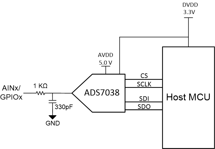
Figure 1-1 shows the ADS7038-Q1EVM input circuity for the analog inputs.
 Figure 1-1 ADS7038-Q1EVM Input Circuity.
 2 ADS7038Q1EVM-PDK Overview
This section describes various onboard components that are used to interface the analog input, general purpose inputs/outputs (GPIOs), digital interface, and provide power supply to the ADS7038-Q1 device.
Figure 2-1 shows an ADS7038Q1EVM-PDK board overview.
 Figure 2-1 ADS7038Q1EVM-PDK Top Layer Overview.
 2.1 Connections to Input Channels
The ADS7038Q1EVM-PDK is designed for easy interface to an external, analog single-ended source, or to GPIOs through a 100-mil header. Connector J5 provides a connection to the device channels. Table 2-1 lists the channel connections. The AIN0 channel features an operational amplifier, TLV9061, to drive the analog input. This is further explained in Section 4. Channels AIN1 through AIN6 have a resistor and capacitor filter circuit to condition the analog input, as Figure 1-1 shows. Channel 7 is hardware configured to demonstrate GPIO functionality. GPIO7 has a resistor and light-emitting diode (LED) to visibly demonstrate and monitor digital output channel state. The LED illuminates when the GPIO7 is logic LOW.
|
J5 Connector Pin |
Description |
|---|---|
|
J5:1 |
Single-ended analog input with buffer |
|
J5:2 |
Single-ended analog input or GPIO for channel 1 of the ADC |
|
J5:5 |
Single-ended analog input or GPIO for channel 2 of the ADC |
|
J5:6 |
Single-ended analog input or GPIO for channel 3 of the ADC |
|
J5:7 |
Single-ended analog input or GPIO for channel 4 of the ADC |
|
J5:8 |
Single-ended analog input or GPIO for channel 5 of the ADC |
|
J5:11 |
Single-ended analog input or GPIO for channel 6 of the ADC |
|
J5:12 |
LED GPO for channel 7 of the ADC |
|
J5:3 and J5:4; J5:9 and J5:10 |
EVM ground |