Design Goals
| Input |
Output |
Supply |
| ViMin |
ViMax |
VoMin |
VoMax |
Vcc |
Vee |
| –1.25V |
+1.25V |
–2.4V |
+2.4V |
+2.5V |
–2.5V |
| Gain |
Cutoff Frequency |
| 6dB (2V/V) to 60dB (1000V/V) |
7kHz |
Design Description
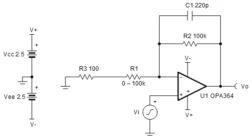
This circuit provides programmable,
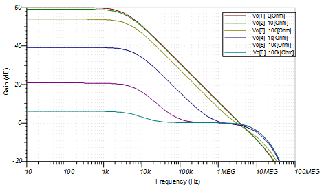
non-inverting gains ranging from 6dB (2V/V) to 60dB (1000V/V) using a variable input
resistance. The design maintains the same cutoff frequency over the gain range.
Design Notes
- Choose a digital potentiometer,
such as TPL0102 for R1 to design a low-cost digital programmable gain
amplifier.
- R3 sets the maximum gain
when R1 approaches 0 Ω.
- A feedback capacitor limits the
bandwidth and prevent stability issues.
- Evaluate stability across the
selected gain range. The minimum gain setting is likely the most sensitive to
stability issues.
- Some digital potentiometers can
vary in absolute value by as much as ±20% so gain calibration may be
necessary.
Design
Steps
- Choose R2 and
R3, to set the maximum gain when R1 approaches 0:
- Choose the potentiometer maximum
value to set the minimum gain:
- Choose the bandwidth with a
feedback capacitor:
- Check for stability at minimum gain
(2V/V), which is when R1=100kΩ. To satisfy the requirement
fc (circuit bandwidth) must be less than fzero (zero
created by the resistive feedback network and the differential and common-mode
input capacitances).
Design
Simulations
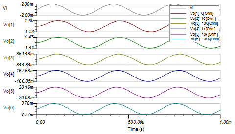
Transient Simulation
Results
Design
Featured Op Amp
| OPA364 |
| Vss |
1.8V to 5.5V |
| VinCM |
Rail-to-rail |
| Vout |
Rail-to-rail |
| Vos |
1mV |
| Iq |
1.1mA |
| Ib |
1pA |
| UGBW |
7MHz |
| SR |
5V/μs |
| #Channels |
1, 2, and 4 |
| OPA364 |
Design Alternate Op Amp
| OPA376 |
| Vss |
2.2V to 5.5V |
| VinCM |
Rail-to-rail |
| Vout |
Rail-to-rail |
| Vos |
5μV |
| Iq |
760μA |
| Ib |
0.2pA |
| UGBW |
5.5MHz |
| SR |
2V/μs |
| #Channels |
1, 2, and 4 |
| OPA376 |


