-
Improving Signal Measurement Accuracy in Automated Test Equipment
Improving Signal Measurement Accuracy in Automated Test Equipment
Application Brief
Test and measurement are two of the critical aspects in the modern day production and development process. Measurement systems have a dual challenge and expectation, being fast and accurate while giving the best performance over lifetime of the system. These systems help capture the information which is used to take a critical and fast decision about the product quality.
Similar challenges are faced in the high resolution data acquisition systems, more so in high precision measurement environment in semiconductor test equipment. Performance of semiconductor test equipment can be measured by 2 key factors, accuracy and precision.
While accuracy deals with the integrity of the signal or how close the measured signal is to the actual signal being measured, precision presents the repeatability of the signal measurement and maintaining limits.
Parametric measurement in semiconductor test equipment
Accurate measurement and recording of the semiconductor parameters is critical to defining the limits and guard band for the semiconductor devices and fast measurement help keep the cycle time and cost low. Parametric measurement unit is critical part of the semiconductor testing equipment which enables accurate current or voltage measurement while applying voltage or current at the DUT at the pin.
This technical article specifically focuses on using the ultra-low-leakage precision multiplexers in order to improve the signal measurement accuracy.
When it comes to precision multiplexer selection, few additional parameters, which are defined in the glossary, are critical to the measurement accuracy and integrity of the signal through the multiplexer device.
- Leakage current (I leakage): The multiplexer leakage current flows through the input impedance (Rsource) which results in the offset error that affects the measurement. Further temperature variations can amplify the offset DC error and introduce linearity errors.
Low leakage current specifications will limit the DC error introduced at the output and optimize the measurement.
- On Capacitance (CON): The on capacitance affects settling behavior of multiplexers and hence transient performance of the system. Higher CON can introduce distortion in systems where input channels are switched at a very fast rate.
- On Resistance (RON): The on resistance of a switch can introduce variations and gain error, which produce signal dependent distortion. RON drifts over temperature limits accuracy and degrades the linearity of VOUT.
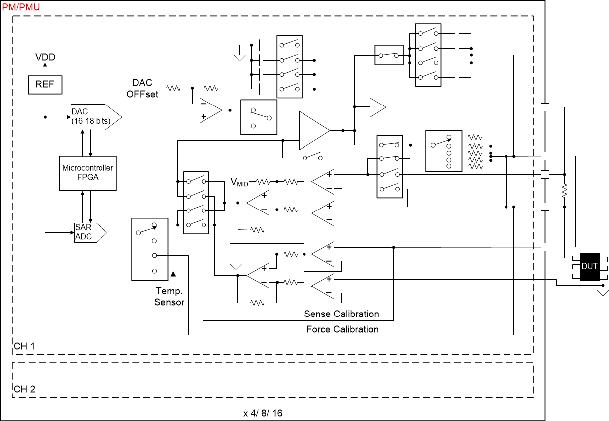
The PMU (Figure 1) is frequently used to characterize and measure the DC characteristics of the digital pin of a device under test (DUT).
 Figure 1-1 Parametric Measurement Unit (PMU) in Automated
Test Equipment (ATE).
 Why a low-leakage-current multiplexer is critical in ATE systems
In ATE systems, the Parametric Measurement Unit (PMU) is tasked to measure device (DUT) parametric information in terms of voltage and current. Among all the capabilities of the PMU: force voltage, measure current (FVMC), and force current, measure voltage (FCMV) are the two most typical configurations in DC characterizations.
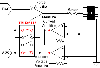
The FVMC configuration is useful to test a device being used as a power supply, or in continuity or leakage testing. In this configuration, the input voltage is directly applied to the DUT pin, and the current into or out of the DUT pin is converted to a voltage by a sense resistor (RSENSE) and measured by an analog to digital converter (ADC). In the FCMV mode, an input current is forced to the DUT and the produced voltage on the DUT pin is directly measured.
 Figure 1-2 Force Voltage Measure
Current.
  Figure 1-3 Force Current Measure
Voltage.
 The FVMC and FCMV modes implementations can be combined with the use of a quad SPST switch such as the TMUX6112. Figure 2 and Figure 3 show simplified diagrams of such implementations. In the FVMC mode, the switch is toggled to a position that allows the voltage sense amplifier to become part of the feedback loop and the voltage output of the current sense amplifier to be sampled by the ADC. In the FCMV mode, the switch is toggled to position that allows the current sense amplifier to become part of the feedback loop and the voltage output of the voltage sense amplifier to be sampled by the ADC.
During this switch toggle operation, it is vital to maintain the integrity of the signal being fed to the ADC and the current and voltage sense amplifiers. Limiting the offset error to bare minimum helps measurement of the signal accurately and fast so as to enable the large scale testing of the semiconductor devices.
Table 1-1 gives some of the high-precision multiplexers to choose from for the applications involving high grade of accuracy such as previously explained.
| Device No. | Configuration | # Channels | RON (Ω) (TYP) | Ron Flatness (Ω) (TYP) | ON State Leakage Current (nA) (TYP) | ON Capacitance CON (pF) (TYP) |
|---|---|---|---|---|---|---|
|
1:1 SPST |
4 |
120 |
2.50 |
0.01 |
4.2 | |
|
1:1 SPST |
8 |
4.5 |
0.50 |
0.05 |
180 | |
|
2:1 SPDT |
1 |
4.0 |
0.45 |
0.04 |
170 |
For more information on offset voltage error and the subsequence loss of bits in an ADC, see the technical article – Does a low-leakage multiplexer really matter in a high-impedance precision data acquisition system?
- End Equipment block diagram and Hero parts
- Texas Instruments, MUX-friendly precision operational amplifiers tech note
- Texas Instruments, Selecting the Right Texas Instruments Signal Switch Application Report
- Texas Instruments, Multiplexers and Signal Switches Glossary
IMPORTANT NOTICE AND DISCLAIMER
| TI PROVIDES TECHNICAL AND RELIABILITY DATA (INCLUDING DATASHEETS), DESIGN RESOURCES (INCLUDING REFERENCE DESIGNS), APPLICATION OR OTHER DESIGN ADVICE, WEB TOOLS, SAFETY INFORMATION, AND OTHER RESOURCES “AS IS” AND WITH ALL FAULTS, AND DISCLAIMS ALL WARRANTIES, EXPRESS AND IMPLIED, INCLUDING WITHOUT LIMITATION ANY IMPLIED WARRANTIES OF MERCHANTABILITY, FITNESS FOR A PARTICULAR PURPOSE OR NON-INFRINGEMENT OF THIRD PARTY INTELLECTUAL PROPERTY RIGHTS. |
| These resources are intended for skilled developers designing with TI products. You are solely responsible for (1) selecting the appropriate TI products for your application, (2) designing, validating and testing your application, and (3) ensuring your application meets applicable standards, and any other safety, security, or other requirements. These resources are subject to change without notice. TI grants you permission to use these resources only for development of an application that uses the TI products described in the resource. Other reproduction and display of these resources is prohibited. No license is granted to any other TI intellectual property right or to any third party intellectual property right. TI disclaims responsibility for, and you will fully indemnify TI and its representatives against, any claims, damages, costs, losses, and liabilities arising out of your use of these resources. |
| TI’s products are provided subject to TI’s Terms of Sale (www.ti.com/legal/termsofsale.html) or other applicable terms available either on ti.com or provided in conjunction with such TI products. TI’s provision of these resources does not expand or otherwise alter TI’s applicable warranties or warranty disclaimers for TI products. |
| Mailing Address: Texas Instruments, Post Office Box 655303, Dallas, Texas 75265
Copyright © 2020, Texas Instruments Incorporated |