SLAA987 February 2021 MSP430FR2433
Application Brief
Watchdog timers (WDTs) are particularly useful because they detect if a microcontroller (MCU) is in an invalid software state and initiate a controlled reset if needed. These invalid software states can be caused by anything from a software bug to electromagnetic interference. In general, an internal WDT resets the device when the reset time interval expires. An external WDT resets the system when it does not receive a regular pulsed signal from the host MCU or processor.
In critical systems, such as smoke detectors and other industrial applications, an invalid software state could be catastrophic. In these instances, an external WDT would be imperative. The external WDT has a separate clock source providing redundancy and making the system more robust. This low-cost solution is based on the MSP430FR2433 MCU and demonstrates a configurable external watchdog timer that accepts reset timeout values ranging from 1 to 5 seconds, in increments of 1 second. If needed, a shorter or longer timeout interval could be achieved by manually changing the timer compare value and the software counter to match the application requirements. When not executing WDT-specific tasks, the MSP430 MCU enters low-power mode 0 (LPM0) to reduce power consumption. To get started, download the project files and example code demonstrating this functionality.
Implementation
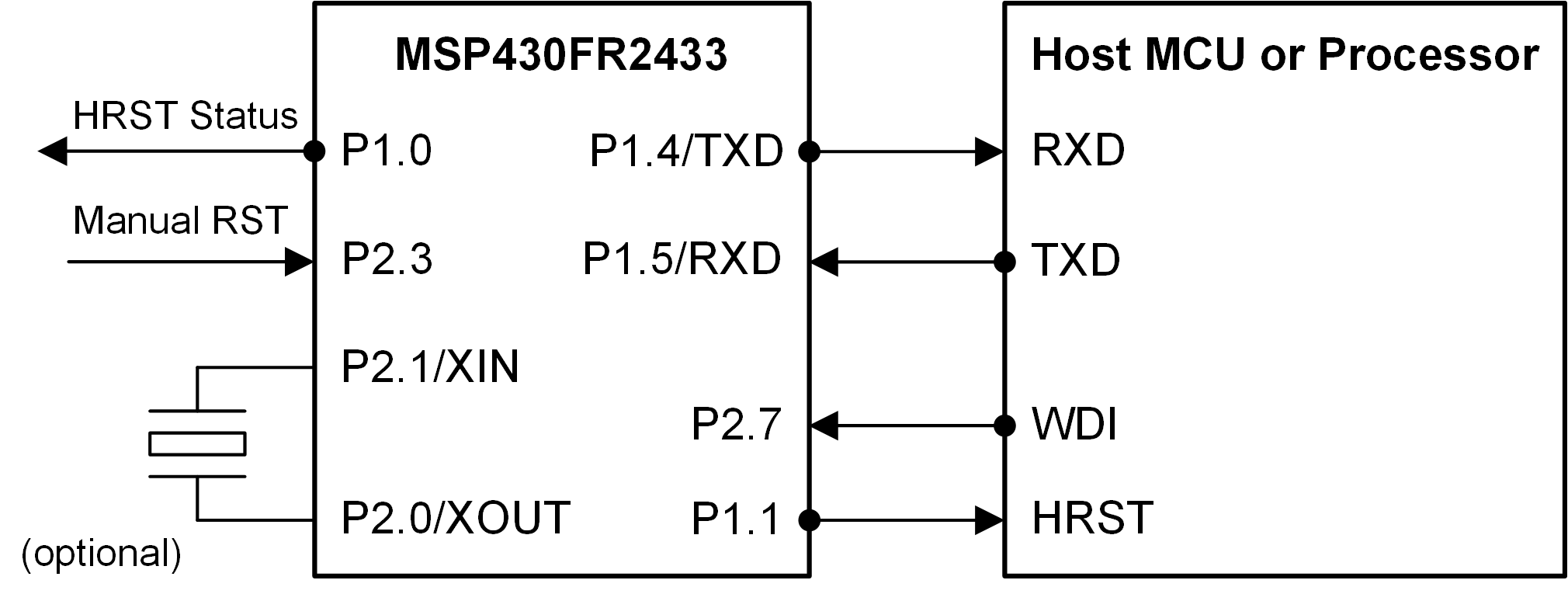
This solution uses the MSP430FR2433 MCU and an external host MCU or processor with a universal asynchronous receiver/transmitter (UART) interface, reset pin and general-purpose inputs/outputs (GPIOs). This allows the reset pin of the host to be controlled by the MCU.
Figure 1-1 shows how the MSP430FR2433 MCU can be connected to a host MCU or processor and function as an external WDT.
 Figure 1-1 External Watchdog Timer Block
Diagram
Figure 1-1 External Watchdog Timer Block
DiagramThe external WDT uses interrupts from the inputs or UART commands to wake up from a low-power mode, execute specific functions and then go back to sleep. When a high-to-low transition is applied to the manual reset (MRST) input, the external WDT resets the host by driving the host reset (HRST) output low and then restarts the timeout interval. The pulse duration of the HRST output, initialized to 1 millisecond, can be adjusted by changing the RESET_CYCLES macro in the source code. The watchdog interrupt (WDI) input is a periodic signal generated by the host to notify the external WDT that it is working properly. A high-to-low transition within every n seconds (specified by the DEFAULT_INTERVAL macro) prevents the external WDT from resetting the host by restarting the timeout interval (commonly referred to as “feeding” the watchdog). The timeout interval is initialized to 5 seconds but can be changed in the source code or over UART. The host can also feed the external WDT or reset itself over UART.
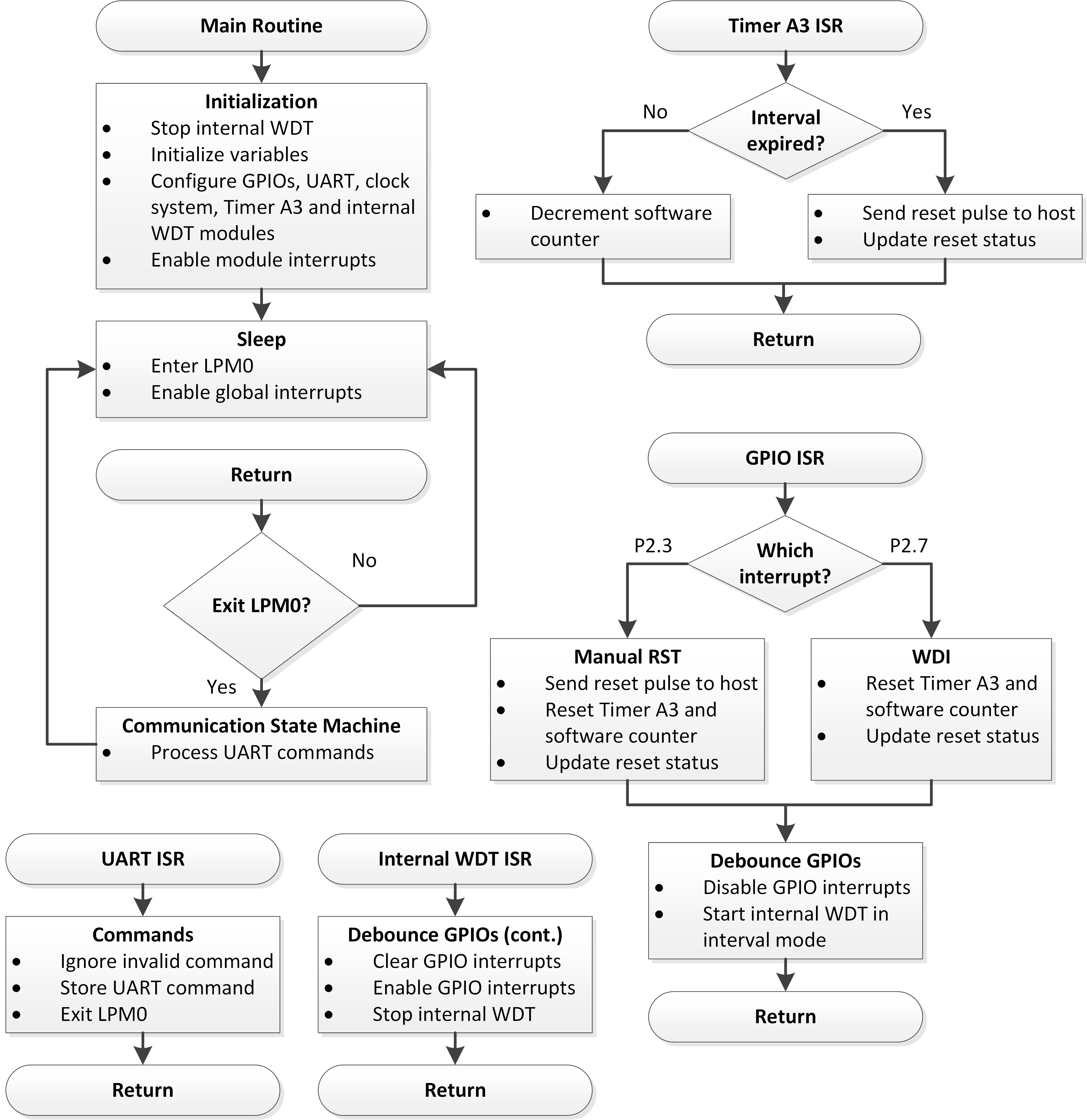
Figure 1-2 shows how the software works with the hardware to reliably monitor a host MCU or processor. The internal WDT module is configured as an interval timer and is used to debounce the GPIO inputs by disabling them for 250 milliseconds before re-enabling them. The Timer A3 module is used in up mode to repeatedly count up to 1 second. Combined with a software counter, they are used to count up to the specified reset timeout interval for the external WDT.
The internal 32768-Hz REFO oscillator is used as the clock source for both of these modules as well as the FLL reference. The 16-MHz subsystem master clock (SMCLK) is used as the clock source for the UART module.
 Figure 1-2 External Watchdog Timer
Software Flowchart
Figure 1-2 External Watchdog Timer
Software FlowchartThe MSP430FR2433 LaunchPad Development Kit was used for testing this solution, but it can be used on any MSP430 MCU with the proper peripheral support and code migration. The LaunchPad’s eZ-FET back-channel UART interface can be connected to a PC terminal program or GUI Composer at 9600 baud (no parity, 1 stop bit) for sending the commands during evaluation and further testing.
Table 1-1 lists the seven valid UART commands in hex format. Invalid commands are ignored.
| UART Command (Hex) | Description |
|---|---|
| 01h | Select timeout interval (1 s) |
| 02h | Select timeout interval (2 s) |
| 03h | Select timeout interval (3 s) |
| 04h | Select timeout interval (4 s) |
| 05h | Select timeout interval (5 s) |
| 06h | Feed timeout interval |
| 07h | Reset host manually |
Performance
This solution uses the internal WDT module for debouncing the GPIO inputs. If the watchdog function is needed by the application, the internal WDT could be configured in watchdog mode, and another instance of the Timer A2 or A3 module could be used for debouncing. For the external WDT, Timer A3 and a software counter count up to the specified reset timeout interval, but the Real-Time Clock (RTC) counter module could be used instead. The internal 32768-Hz REFO oscillator is used as the auxiliary clock (ACLK) source. Alternatively, an external 32768-Hz crystal could be used as the ACLK source to improve timing accuracy and reduce power consumption if the crystal selection resistors are changed on the MSP430FR2433 LaunchPad Development Kit and the __ENABLE_XT1__ symbol is added to the compiler settings in the CCS project. The existing UART protocol could be changed to include data packets containing a more precise timeout interval (for example, milliseconds rather than seconds) if needed.
To run the demo, connect the MSP430FR2433 LaunchPad Development Kit to the PC and program the device using the standalone or GUI source code. To evaluate either demo without a host, buttons and LEDs on the LaunchPad can be used as the inputs and outputs of the external WDT, respectively. The S1 button is connected to the MRST input, P2.3, and the S2 button is connected to the WDI input, P2.7. Populate JP10 to connect LED1 to the host reset status output, P1.0. Populate JP11 to connect LED2 to the HRST output, P1.1. These LEDs are helpful indicators when evaluating the demos.
At start-up, the code turns off LED1 (active high), turns on LED2 (active low) and starts counting up to the reset timeout interval. If no high-to-low transitions are applied to the WDI input before the timeout interval expires, the HRST output is pulsed low. LED1 turns on indicating a reset has occurred, and the code continues to send reset pulses to the host. Pressing S2 feeds the external WDT by restarting the timeout interval, which turns off LED1. Pressing S1 manually resets the host, which turns on LED1 briefly, and restarts the timeout interval.
For the standalone demo, a PC terminal program (for example, Docklight, Tera Term, and so forth) can be used as the host and send the UART commands in Table 1-1 to the external WDT. Commands 01h to 05h change the timeout interval. Commands 06h and 07h can be used to feed the external WDT and manually reset the host, respectively. These UART commands can also be implemented on the host MCU or processor.
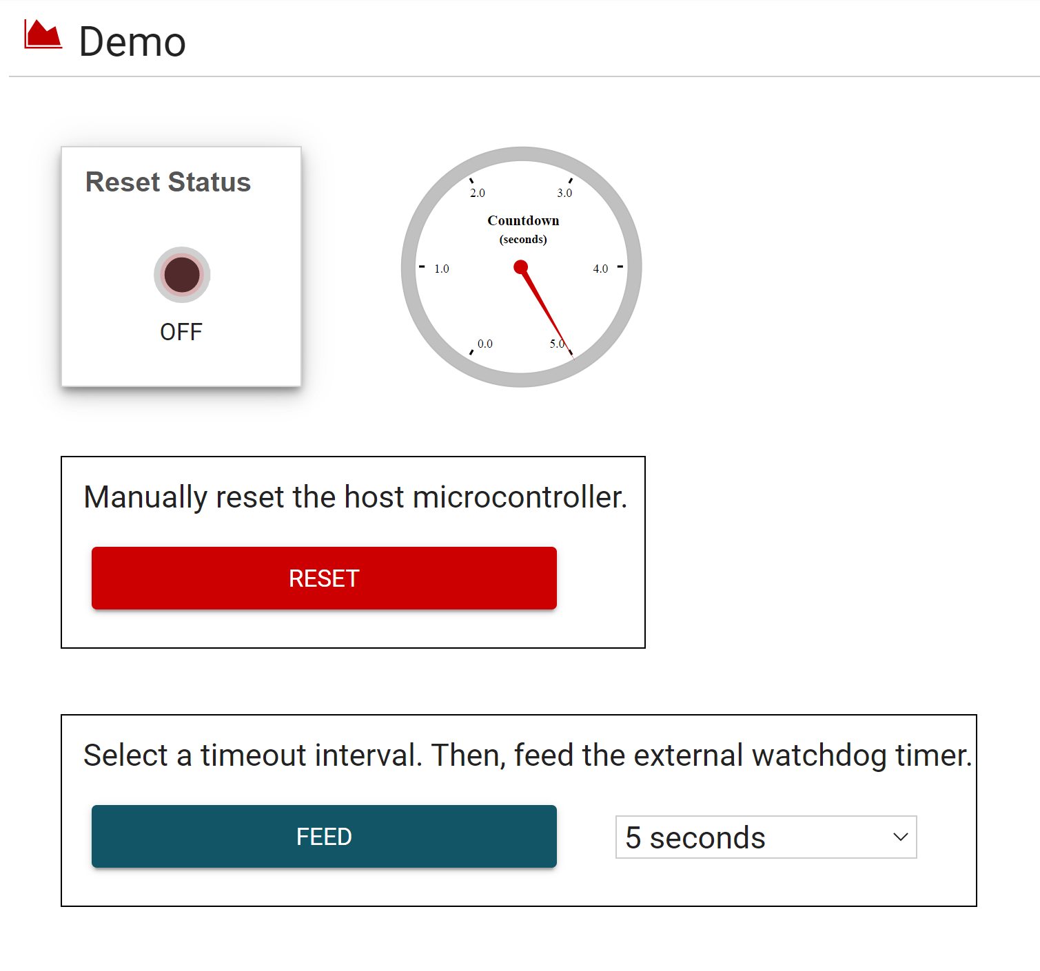
For the GUI demo, the GUI can be used as the host as shown in Figure 1-3. After connecting the LaunchPad to the PC, press the S3 button on the LaunchPad to reset the MSP430 MCU. In the GUI, the Reset Status LED should turn off and the timeout interval should start counting down from 5 seconds. If the timeout interval expires, the Reset Status LED turns on, just like LED1 on the LaunchPad, indicating that the external WDT has reset the host. Clicking the RESET button will manually reset the host, restart the countdown and turn off the Reset Status LED. Clicking the FEED button before the countdown stops will keep the Reset Status LED off and restart the countdown, which prevents the external WDT from resetting the host. If needed, select a different timeout interval using the drop-down menu. Remember that both demos also support inputs from the S1 and S2 buttons on the LaunchPad and signals from a host MCU or processor.
 Figure 1-3 External Watchdog Timer GUI
Demo
Figure 1-3 External Watchdog Timer GUI
DemoTo Get Started
- Watch the training video “External Programmable Watchdog Timer using a Housekeeping MCU” to learn how to use the GUI to manually reset the host and feed the external WDT.
- Order a MSP430FR2433 LaunchPad Development Kit to evaluate the External Programmable Watchdog Timer example GUI and code.
- Download and test the External Programmable Watchdog Timer example GUI to easily adjust the timeout interval and feed the external WDT.
- Evaluate the External Programmable Watchdog Timer example code using the MSP430FR2433 LaunchPad Development Kit.
| Part Number | Key Features |
|---|---|
| MSP430FR2433 | 16KB FRAM, 4KB SRAM, 10-bit ADC, UART/SPI/I2C, Timer |
| MSP430FR2422 | 8KB FRAM, 2KB SRAM, 10-bit ADC, UART/SPI/I2C, Timer |