SLAAE42 September 2021 MSP430FR2433
1 Implementation
In this solution, ACLK is sourced from XT1 external crystal oscillator which frequency is 32768Hz. SMCLK and MCLK is 1 MHz as default. The RTC counter is sourced from XT1 external crystal oscillator. The source clock of the universal serial communication interface (eUSCI) UART is selected as 1 MHz SMCLK.
Implementation
The RTC counter functions in AM and all LPMs except LPM4.5. So MCU will enter LPM3.5 to reduce consumption when it is idle. In LPM3.5, RTC counter accepts only XT1CLK or VLOCLK as its clock source to periodically wake up the device. The RTC counter can generate an interrupt when the counter value overflows at the value set by user. MCU will be woken up by interrupt to update the calendar, then enter LPM3.5 again.
Pin P2.3 detects the tamper event. An interrupt is triggered at the rising edge or falling edge. MCU will be woken up by interrupt to execute pre-set operation (In this example, P1.0 is set) and record the time stamp of that moment, then enter LPM3.5 again.
Pin P2.7 is used to be triggered to enter the calendar editable mode. In the calendar editable mode, the microcontroller remains active, waiting to receive data from the host. When the finish editing command is received, it will return to the non-editable calendar mode and enter low power mode. LED of P1.1 shows the status of calendar edit mode.
The Real-Time Clock Library is used in the application. The RTC library encapsulates commonly used routines for keeping track of time. These functions are written in assembly to be optimized for the MSP430, but can be called from any C program that includes the RTC.h header file. In a one-second interrupt triggered by RTC, the function is called and the calendar is updated. And Variables that store calendar information can be read directly. For more information about the Real-Time Clock Library, see Using the Real-Time-Clock Library (Rev. A).
The low-power modes LPM3.5 and LPM4.5 (LPMx.5) give the lowest power consumption on a device.
In LPM3.5, most of the modules are powered down, only modules powered by the RTC LDO continue to operate. At least an RTC module is connected to the RTC LDO. After a wakeup, the register content, the CPU and the SRAM content are lost, So the application must initialize the complete device. To prevent data loss and simplify the wake-up process, Compute Through Power Loss (CTPL) can be used.
Compute Through Power Loss (CTPL) is a software-utility library for Ultra-Low-Power MSP430FRxx FRAM microcontrollers. The CPTL enables an application to easily save the CPU and peripheral states into nonvolatile FRAM before powering down or entering a deep-sleep mode like LPMx.5. When a CPU wakes up, the CTPL restores an application exactly where it last executed with context-save and restore. More information about CTPL can be found in MSP-EXP430FR6989 & FRAM to Enable Compute Thru Power Loss Utility Design Guide.
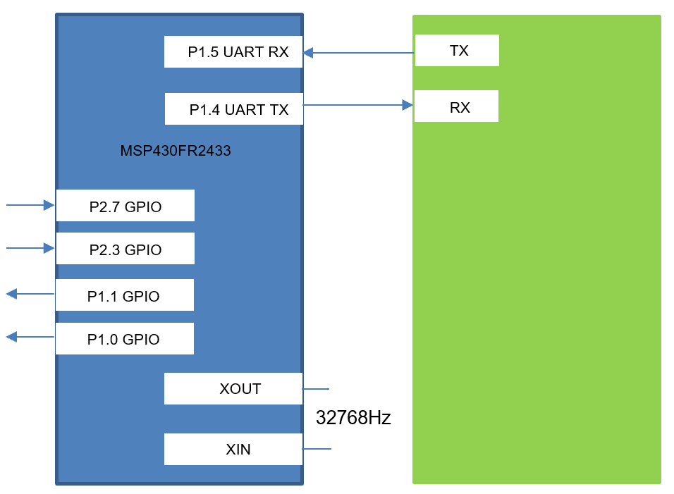
Figure 1-1 shows the block diagram for this implementation.
 Figure 1-1 Block Diagram
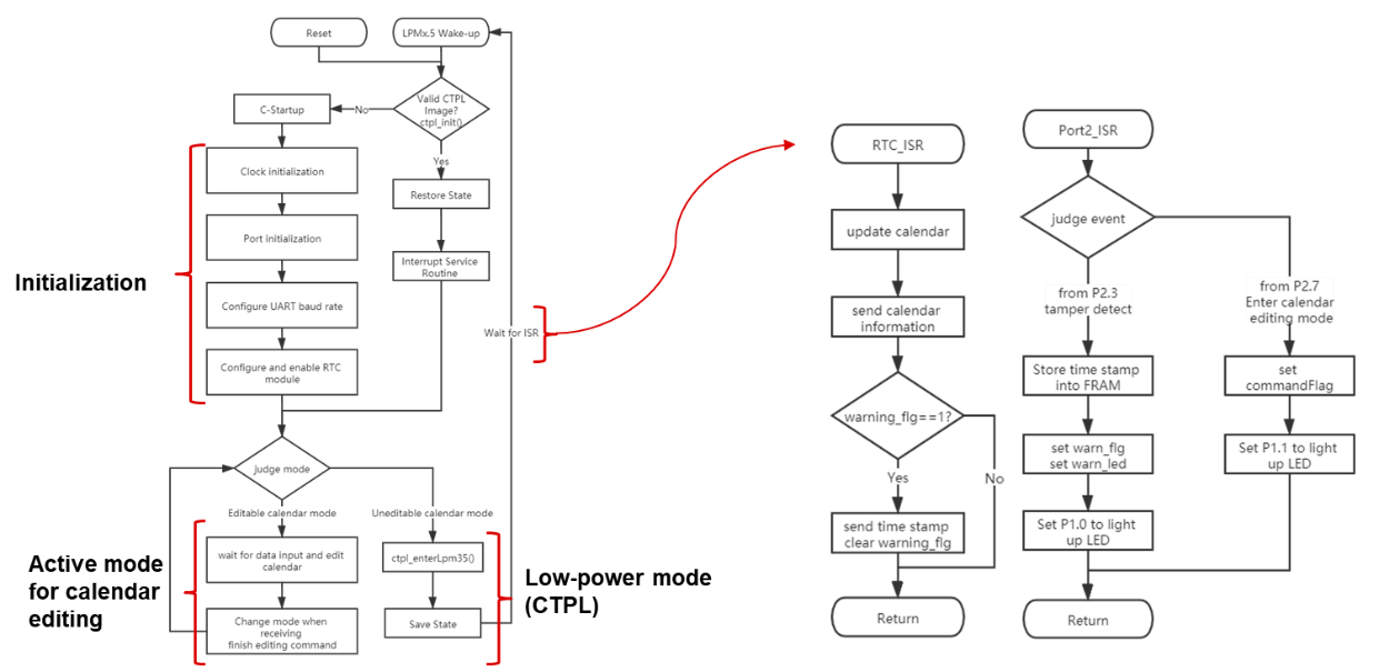
Example code flow chart is shown as Figure 1-2. In the main program flow chart, after initialization the microcontroller is in non-editable calendar mode. It enters low-power mode, and waits for interrupt requests triggered by peripheral events.
The first interrupt request comes from the RTC module. It is set to once every 1 second. It is used to update the calendar and send data to host through UART.
The second interrupt request comes from the Port. Port P2.3 is used to detect tamper events. Port P2.7 is used to be triggered to enter the calendar editable mode.
In the calendar editable mode, the microcontroller remains active. It waits to receive data from the host. When the finish editing command is received, microcontroller will return to the non-editable calendar mode, and enter low power mode.
 Figure 1-2 Example Code Flow
Chart
Figure 1-2 Example Code Flow
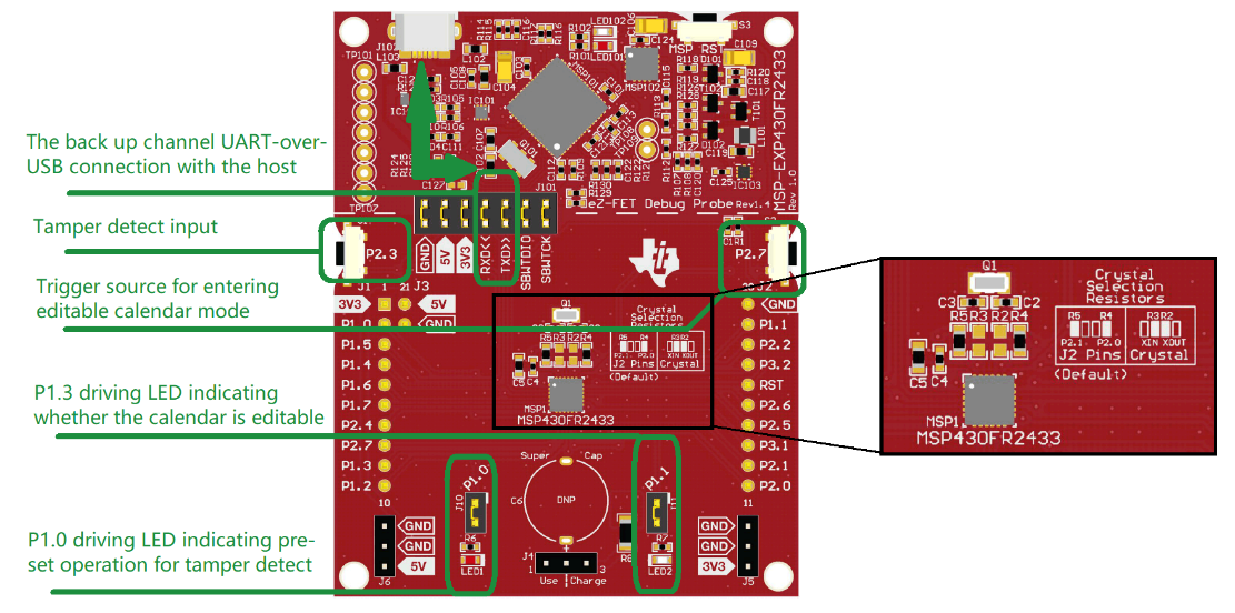
ChartThe MSP430FR2433 LaunchPad™ Development Kit can be used on this example project. back-channel UART interface on eZ-FET of the LaunchPad can be used on UART communication with GUI. The COM channel number information can be found on the device management of the control panel.
Figure 1-3 MSP430FR2433 LaunchPad Resistor Selection for Onboard 32-kHz Crystal. tamper detect input by P2.3, triggered by P2.7 to enter editable calendar mode, LED driven by P1.0 and P1.1
 Figure 1-3 Missing Title
The GUI is used to receive and show the calendar information and time stamp. When it is in editable calendar mode, GUI can edit the calendar, which is updated immediately. The eUSCI_A0 peripheral was used in UART mode to enable commands to be received on P1.5/UCA0RXD and transmitted on P1.4/UCA0TXD. The eZ-FET inside of LaunchPad was used for evaluation. A baud rate of 9600 must be selected with one stop bit and no parity.
Performance
The operation of the demo can be run as described in the implementation section regarding the use of UART to edit the calendar and receive the calendar information or time stamp. P2.3 is used for the tamper detect input. P2.7 is used to be triggered to enter the editable calendar mode.
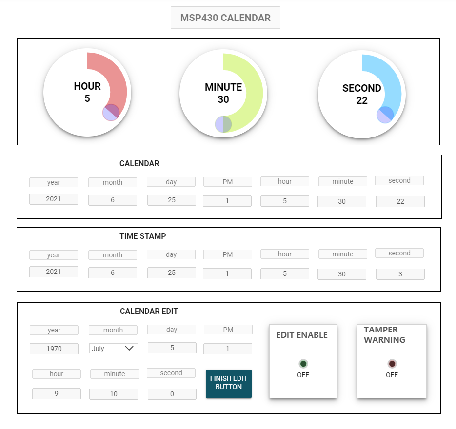
The GUI interface is shown as Figure 1-4. In the first row, three dials display clock information such as hours, minutes and seconds. In the second row, text boxes display the complete calendar information. They both are updated in real time. In the third row, Text boxes display the time stamp, which are updated only if a tamper is detected. And the red LED lights up to indicate the tamper event. In the fourth row, when it is in editable calendar mode, the text boxes will become editable, and the green light will light up. Editing the text box will immediately change the calendar. By pressing the FINISH EDIT BUTTON to exit the editable calendar mode, the text box will be non-editable, and the green light will go out.
“ENABLE_GUI” pre-definition on CCS project is the flag to set the example code supporting GUI or not.
 Figure 1-4 GUI View
The average power consumption of the programmable system wake-up controller is around 0.9 μA. The average current of the application is dominated by the LPM3.5 current of the device and approaches this level as the wake-up time period is extended.
The size of code with GUI is 11200 bytes. The size of code without GUI is 7292 bytes.
To Get Started
- Watch the training video “Calendar and Tamper Detect with a Housekeeping MCU” to learn how to use the GUI to observe the calendar and use the function of tamper detect.
- Order a MSP430FR2433 LaunchPad kit to evaluate the Calendar and Tamper Detect example code.
- Download and test this example with the Calendar and Tamper Detect example GUI to receive the calendar information or tamper information, and edit the calendar simply.
- Evaluate the Calendar and Tamper Detect example code for the MSP430FR2433 LaunchPad kit.
Device Recommendations
The device used in this example is part of the MSP430 housekeeping portfolio. This example can be used with the devices shown in Table 1-1 with minimal code changes.
| Part Number | Key Features |
|---|---|
| MSP430FR2433 | 16KB FRAM, 4KB SRAM, 10-bit ADC, UART/SPI/I2C, Timer |
| MSP430FR2422 | 8KB FRAM, 2KB SRAM, 10-bit ADC, UART/SPI/I2C, Timer |