SLVAEY7 September 2020 TPS3899
Application Brief
This technical note expands on the Programmable Push-Button, Pulse Detector, and Pulse Generator Solutions (SBVA061) applications note and discusses the sense delay programmable timing feature added with the TPS3899 voltage supervisor.
The sense delay is the delay time for which the sense voltage needs to be under the voltage threshold in order to assert a reset. On previous TI voltage supervisors this delay was small and fixed, however, on the TPS3899, sense delay time can be programmed from several hundred microseconds up to several seconds.
There are many applications for which a sense delay would be useful. One application of sense delay is minimum pulse width detection which is useful for push-button holding functionality, control systems, communications, timing measurement devices, and timing fault detections. Another application is preventing false resets on noisy voltages.
Push-Button with Holding Requirements
One application of minimum pulse width detection using the TPS3899 is a push-button that needs to be held for a duration of time in order to activate.
Voltage supervisors when used for push-button programming typically have programmability on the deassertion of a reset but not on the assertion of a reset. The TPS3899 voltage supervisor has the CTR pin for programming deassertion delay (reset delay) and the additional CTS pin for programming assertion delay (sense delay).
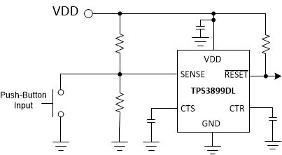
Using the TPS3899, a push-button can now be programmed to have a user-customized hold requirement before the signal can be asserted. The typical topology of this circuit using the open-drain active low variant of TPS3899 is shown in Figure 1-1 (Note: If using the push-pull variants pull-up resistor on the reset output will need to be removed).
 Figure 1-1 Programmable Push-button
Circuit Using TPS3899
Figure 1-1 Programmable Push-button
Circuit Using TPS3899The RESET output will be inputted to the desired device as a “button pressed” signal and will only be asserted if the push-button is held down for the minimum length of programmed time. The push-button is connected to the sense pin and ground.
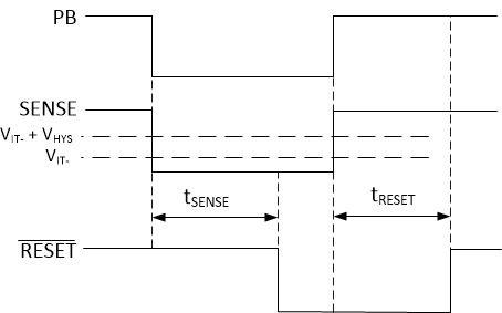
When pressed, the push-button will tie the sense pin to ground causing VSENSE to be lower than the input threshold voltage. If the button is pressed for the duration of tSENSE, then the RESET output will assert. After the button is released, the RESET output will deassert after the duration of tRESET. See Figure 1-2 for the timing diagram of a button press.
 Figure 1-2 Programmable Push-button
Circuit Timing Diagram
Figure 1-2 Programmable Push-button
Circuit Timing DiagramtSENSE and tRESET are programmed through the capacitor values placed on the CTS and CTR pins respectively. Placing a larger capacitor on the pin increases the delays and placing a smaller capacitor decreases the delay.
See Table 1-1 for example options on the push-button timing. By adjusting the capacitor on CTS, the hold requirement for the push-button changes. For example, placing a 10µF capacitor on CTS makes the hold requirement for the push-button 6.19s.
|
tSENSE (Sense Delay) |
tRESET (Reset Delay) |
|
|---|---|---|
|
CTS = 0.1 µF, CTR = 0.1µF |
61.9ms |
61.9ms |
|
CTS = 1µF, CTR = 1uF |
619ms |
619ms |
|
CTS = 10 µF, CTR = 10 µF (max.) |
6.19s |
6.19s |